Optical lens, optical module having the same, and backlight assembly having the same

a technology of optical modules and backlights, applied in the field of optical modules having optical lenses, can solve the problems of increasing manufacturing costs, and achieve the effects of reducing the number of optical modules in the display device, reducing manufacturing costs, and increasing effective light emitting radius

Active Publication Date: 2006-10-12
SAMSUNG DISPLAY CO LTD
View PDF6 Cites 23 Cited by
  • Summary
  • Abstract
  • Description
  • Claims
  • Application Information

AI Technical Summary

Benefits of technology

[0017] The optical lens according to the present invention has an increased effective light emitting radius, so that the number of optical modules in the display device may be reduced to

Problems solved by technology

However, in order to get uniform luminance by using the LEDs, the LCD apparat

Method used


Image

  • Optical lens, optical module having the same, and backlight assembly having the same
  • Optical lens, optical module having the same, and backlight assembly having the same
  • Optical lens, optical module having the same, and backlight assembly having the same

Examples


Embodiment Construction

[0028] It should be understood that the exemplary embodiments of the present invention described below may be varied modified in many different ways without departing from the inventive principles disclosed herein, and the scope of the present invention is therefore not limited to these particular flowing embodiments. Rather, these embodiments are provided so that this disclosure will be thorough and complete, and will fully convey the concept of the invention to those skilled in the art by way of example and not of limitation.

[0029] Hereinafter, the embodiments of the present invention will be described in detail with reference to the accompanied drawings.

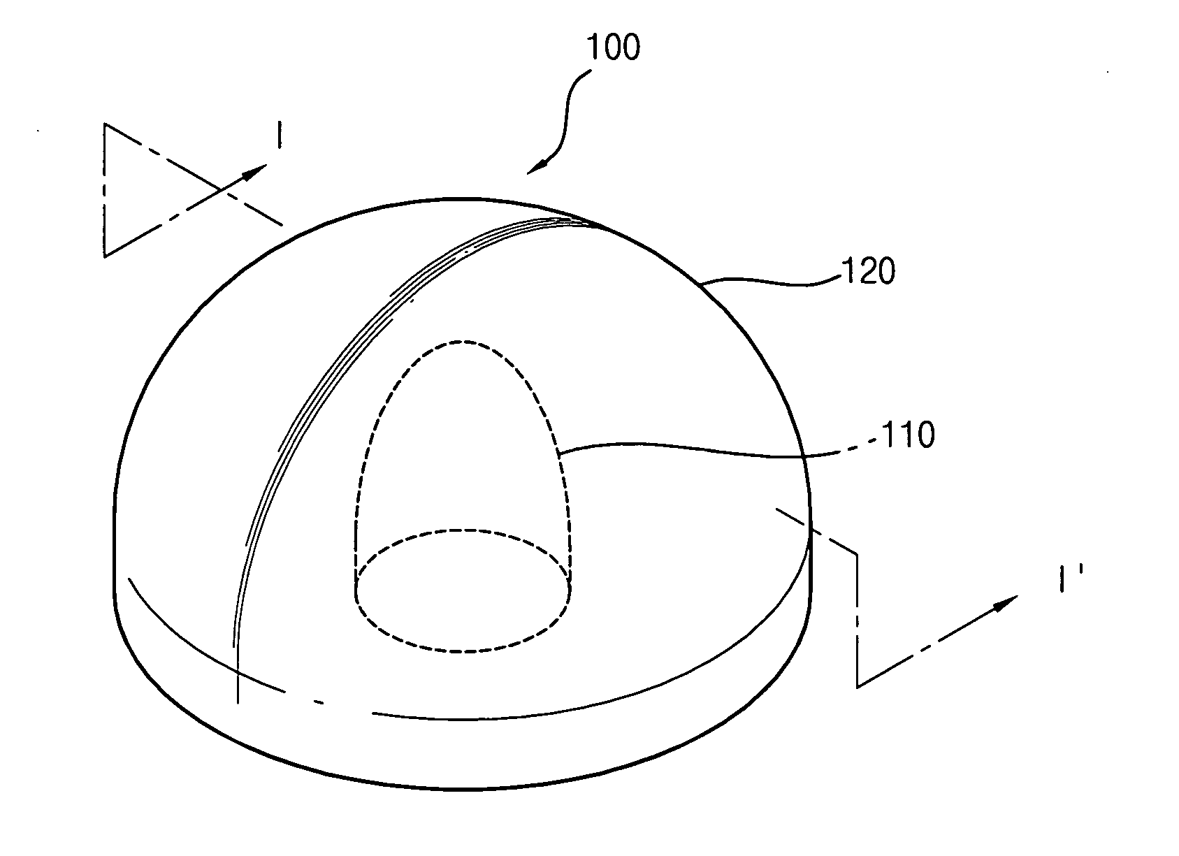
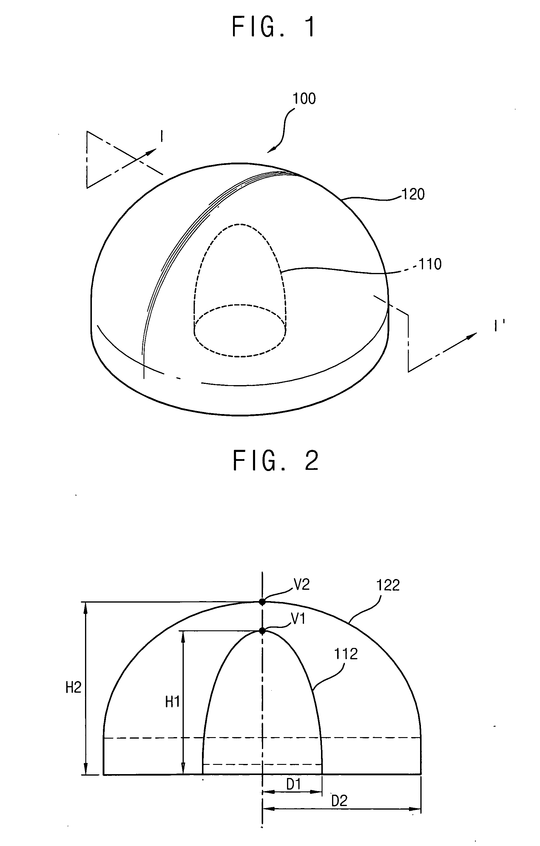
[0030]FIG. 1 is a perspective view illustrating an optical lens according to an exemplary embodiment of the present invention, and FIG. 2 is a cross-sectional view taken along a line I-I′ in FIG. 1.

[0031] Referring to FIGS. 1 and 2, an optical lens 100 according to an exemplary embodiment of the present invention includes a hol...


PUM


Abstract

An optical module includes a point light source device and an optical lens. The point light source device generates light. The optical lens includes an inner curved surface and an outer curved surface. The inner curved surface has a first roughly ellipsoidal shape having a first major axis and a first minor axis that is substantially perpendicular to the first major axis. The outer curved surface has a second roughly ellipsoidal shape having a second major axis that is substantially perpendicular to the first axis and the second minor axis that is substantially perpendicular to the second major axis. The light generated by the point light source device enters the optical lens through the inner curved surface and exits from the optical lens through the outer curved surface. Therefore, the number of optical modules used in a display device may be reduced to lower manufacturing cost thereof.

Description

CROSS-REFERENCE TO RELATED APPLICATIONS [0001] This application relies for priority upon Korean Patent Application No. 2005-28630 filed on Apr. 6, 2005, the contents of which are herein incorporated by reference in its entirety. BACKGROUND [0002] 1. Field of the Invention [0003] The present invention relates to an optical lens, an optical module having the optical lens, and a backlight assembly having the optical lens. [0004] 2. Description of the Related Art [0005] A display device converts an electric signal processed by an information processing device into a visible image. Examples of display devices include a cathode ray tube (CRT) apparatus, a plasma display panel (PDP) apparatus, a liquid crystal display (LCD) apparatus, an electro-luminance (EL) apparatus, etc. [0006] The LCD apparatus displays an image by using electrical and optical characteristics of liquid crystal. The LCD apparatus is lightweight, has a low driving voltage, and low power consumption, etc. Therefore, the...

Claims


Application Information

Patent Timeline
IPC IPC(8): G02B13/18H01L33/58
CPCG02B3/04A47G11/004A47J47/16
Inventor YOON, JU-YOUNGPARK, HYE-EUNKIM, CHANG-JUKIM, HYUN-JINKIM, GI-CHERLLEE, SANG-YU
Owner SAMSUNG DISPLAY CO LTD
Why Eureka
Try Eureka