Gas discharge laser output light beam parameter control

a technology of laser output and parameter control, which is applied in the direction of laser details, electrical equipment, active medium materials, etc., can solve problems such as unfavorable operation

Inactive Publication Date: 2006-10-12
CYMER INC
View PDF28 Cites 35 Cited by
  • Summary
  • Abstract
  • Description
  • Claims
  • Application Information

AI Technical Summary

Problems solved by technology

However, this is not a favorable state of operation since, once one drops the blower speed one cannot fire again at a relatively higher repetition rate until the blower is spun up again to accommodate, e.g., for the needed arc free blower speed for the higher pulse repetition rate.

Method used


Image

  • Gas discharge laser output light beam parameter control
  • Gas discharge laser output light beam parameter control
  • Gas discharge laser output light beam parameter control

Examples


Embodiment Construction

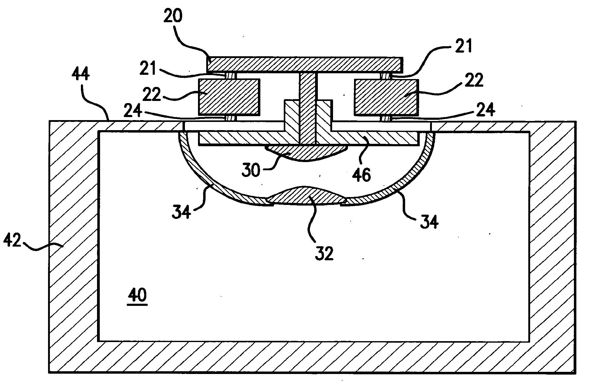
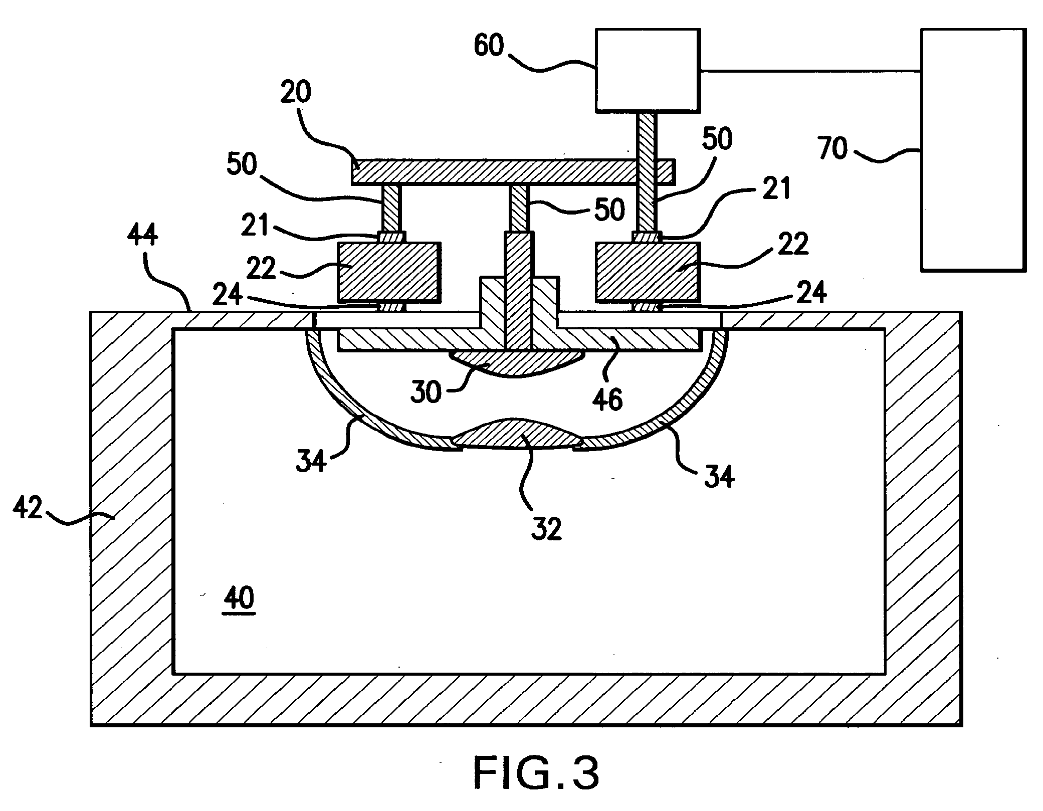
[0022] Applicants have determined that the inductance of the discharge chamber in a gas discharge laser can affect the temporal characteristic of the laser pulse in such way that it increases spectral bandwidth in a monotonic way over a reasonably wide range. the inductance is formed by the physical elements of the discharge electrical path forming a loop that has a natural inductance. The loop is formed from a high voltage bus 20 on one terminal 21 of a capacitor bank of peaking capacitors 22 in parallel, supplying a high voltage, e.g., around 20,000 volts to a cathode electrode 30, then through the discharge itself to an anode electrode 32 which is grounded to the chamber 40 body 42 in electrical contact with the grounded terminal 24 of the capacitor bank through a plurality of current return tines 34 connected between an anode support bar (not shown in FIGS. 1-3, holding the anode 32 opposite the cathode 30, and the grounded chamber top or head 44. The chamber head and the ground...


PUM


Abstract

A line narrowed gas discharge laser system and method of operation are disclosed which may comprise: an oscillator cavity; a laser chamber comprising a chamber housing containing a lasing medium gas; at least one peaking capacitor electrically connected to the chamber housing and to a first one of a pair of electrodes; a second one of the pair of electrodes connected to an opposite terminal of the at least one peaking capacitor; a current return path connected to the chamber housing; the one terminal, the first one of the electrodes, the lasing medium gas, the second one of the electrodes, the current return path and the second terminal forming a head current inductive loop having an inductance unique to the particular head current inductive loo; a spectral quality tuning mechanism comprising a mechanism for changing the particular head current inductive loop inductance value for the particular head current inductance loop.

Description

FIELD OF THE INVENTION [0001] The present invention related to gas discharge lasers utilized in application where very precise control of gas discharge laser output light pulse beam (also refer to as simply a pulsed laser output beam) parameters, e.g., wavelength, bandwidth and dose stability, e.g., within some relatively precisely defined range of values, for applications, such as, integrated circuit photolithography. BACKGROUND OF THE INVENTION [0002] Techniques have been used to control higher harmonic vibration and noise in helicopters, and adaptive noise cancellation, which is widely used. Applicants propose utilizations in the field of gas discharge laser output light pulse beam pulse parameter modification and control. [0003] Reducing the blower speed more or less drastically at low laser output light pulse beam pulse repetition rates may improve the low repetition rate stability of earlier ArF lasers. However, this is not a favorable state of operation since, once one drops ...

Claims


Application Information

Patent Timeline
Patent Type & Authority Applications(United States)
IPC IPC(8): H01S3/22
CPCH01S3/036H01S3/038H01S3/134H01S3/09702H01S3/097
Inventor BESAUCELE, HERVE A.FOMENKOV, IGOR V.PARTLO, WILLIAM N.TRINTCHOUK, FEDOR B.TON THAT, HAO
Owner CYMER INC
Why Eureka
Try Eureka