
High chroma optically variable color-shifting glitter

a color-shifting and glittering technology, applied in the field of optically variable color-shifting glitter particles, can solve the problems of non-opaque glitter particles that are not very high chroma or reflectivity, take up valuable space without providing any percevable glittery effect, and tend to be faint and washed out in appearance, so as to prevent particles from curling and lessen the effect of chipping and breaking

Inactive Publication Date: 2006-10-12
JDS UNIPHASE CORP
View PDF30 Cites 19 Cited by
  • Summary
  • Abstract
  • Description
  • Claims
  • Application Information

AI Technical Summary

Benefits of technology

[0015] It is also desirous to have glitter particles which are at least 30 microns in size, and which have excellent color shifting qualities and high chroma as well as high reflectivity.
[0017] It is therefore an object of this invention to provide glitter which has high chroma, is opaque, and which can be manufactured in a desired shape with a very even size distribution, and wherein the particles are large enough and flat enough to be recognized as glitter.
[0018] It is also an object of this invention, to provide a glitter which both provides a strong glitter effect when the object is stationary, and which provides a high degree of chroma and strong color shifting effects when the object or light source upon the object is moved.
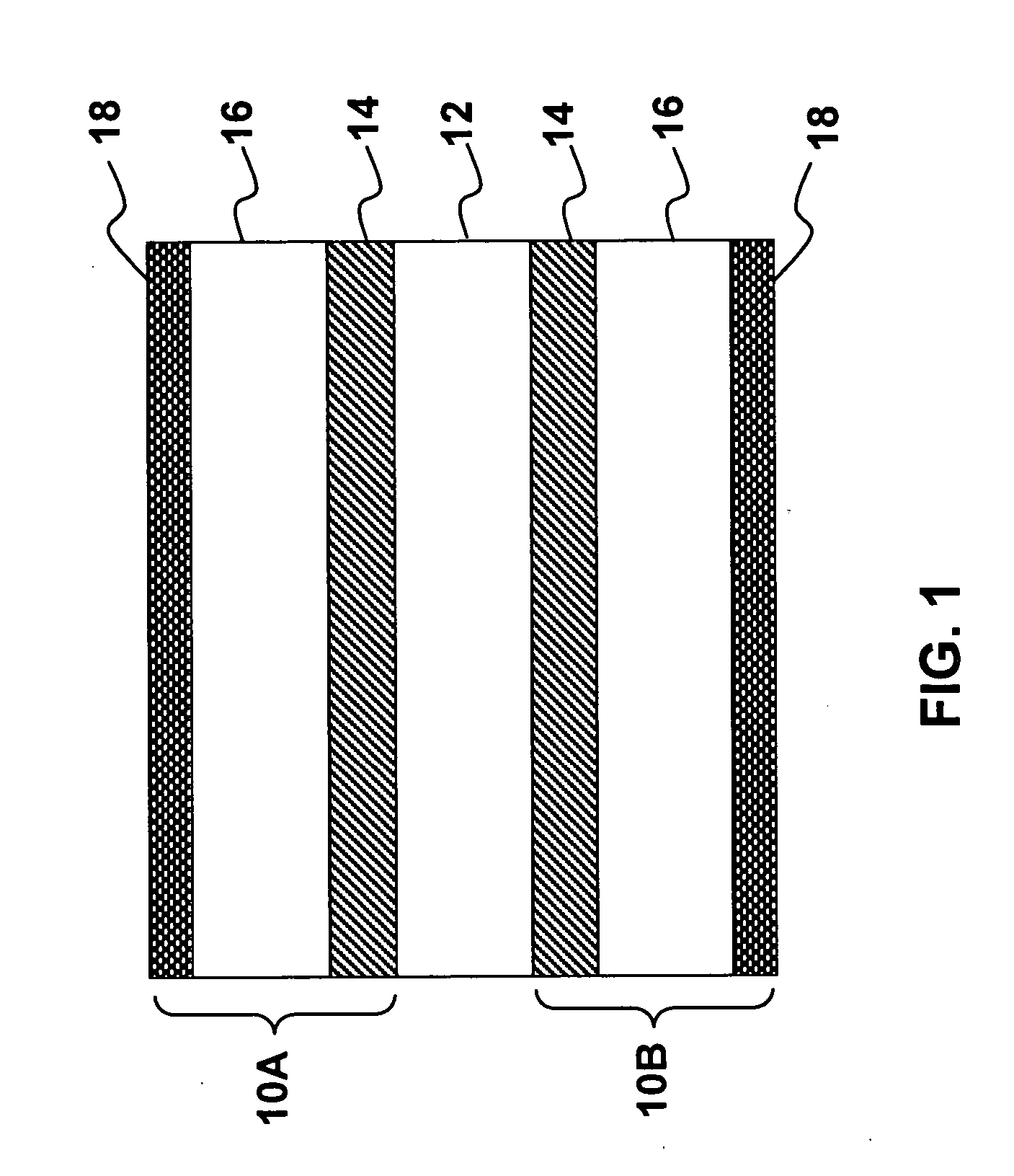
[0021] In accordance with this invention these glitter particles preferably each have a diameter “d” of at least 30 microns, and a thickness “t” of more than 6 microns wherein t<d / 2 . The organic support layer provides rigidity for preventing the color shift coating from curling, for allowing precise cutting of the glitter substrate into discreet particle size and or lessening chipping and breaking of the interference coatings.
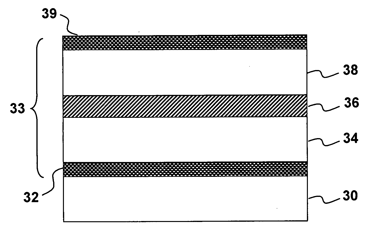
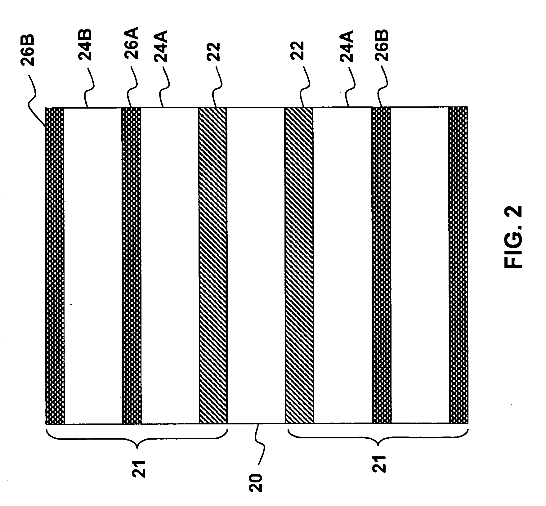
[0024] In accordance with an aspect of this invention, an opaque color-shifting glitter is provided, comprising a plurality of glitter particles, wherein the glitter particles each comprise an organic support layer carrying on each side thereof, a reflector layer, a dielectric layer and an absorber layer, said particles each having an diameter “d” of at least 30 microns, and a thickness “t” of more than 6 microns wherein t<d / 2, the organic support layer providing rigidity for preventing the particles from curling and for lessening chipping and breaking of the particles.
[0025] In accordance with this invention an opaque color shifting glitter is provided comprising glitter particles that have been produced by mechanical means or by a laser inscribing tool such that their shape and size is substantially uniform, said glitter particles each comprising an inorganic thin film optical interference structure providing a perceivable color shift with a change in viewing angle or angle of incident light, in the visible spectrum, wherein said inorganic thin film interference structure of each particle is supported by an organic support layer for providing rigidity and for preventing the particles from curling.

Problems solved by technology

Non-opaque glitter particles tend to be faint and washed-out in appearance.
In contrast, if particles are too small, they simply take up valuable space without providing any perceivable glittery effect.
Although the invention described by Whitney et al. appears to function as intended, the structure is non-opaque and does not provide very high chroma or reflectivity.
The color shifting that is provided tends to be within a range of two washed-out appearing colors, thus the overall effect is not particularly striking.
Although the large particles are desirous for use as glitter, the size in which particles break cannot be accurately controlled and tend to be too small on average.
Furthermore, particles having large diameters tend to curl, losing their ability to serve as high quality glitter which needs to be relatively flat.
The applicant has found that by using conventional techniques used to make color shifting pigments used in paints or inks, high quality glitter cannot be made as the particle distribution, size and flatness required for glitter cannot be met.

Method used


Image

  • High chroma optically variable color-shifting glitter
  • High chroma optically variable color-shifting glitter
  • High chroma optically variable color-shifting glitter

Examples


example 1

[0068] A comparison study between optically variable flakes and color shifting glitter particles:

[0069] Samples were prepared as painted draw-downs as follows:

[0070] Gold to Silver (GO-SL), Blue to Red (BL-RD) and Red to Gold (RD-GO) optical variable thin film coatings were prepared as optically variable flake and optically variable glitter. The designs were of the Fabry-Perot type having the structure: Cr / MgF2 / Al / MgF2 / Cr. The spacer layer thickness was adjusted to obtain the correct color shift as per the known structures in the aforementioned patents.

[0071] The glitter samples in the micrographs shown in FIG. 9a, 9b and 9c and each have a 1 mil thick polyester foil attached to an inorganic optical multilayer stack. In the prior art the optically variable flake is absent the organic polyester film. The optically variable flake samples have a D50 (50% of particles larger than 20 microns and 50% smaller) of 20 microns, with a D0.01 (99.9% of particles larger than 4 microns) of 4 m...


PUM

PropertyMeasurementUnit
Thicknessaaaaaaaaaa
Thicknessaaaaaaaaaa
Lengthaaaaaaaaaa

Abstract

Opaque glitter particles that are uniform in size and shape are disclosed that have an optically variable color with a change in angle of incident light. The glitter particles have an organic substrate and an optical interference structure on one or both sides of the organic substrate. The optical interference design can be a Fabry-Perot structure or can be an optically variable ink.

Description

CROSS-REFERENCE TO RELATED APPLICATIONS [0001] The present invention claims priority from U.S. Patent Application No. 60 / 668,852 filed Apr. 6, 2005 and U.S. Patent Application No. 60 / 694,407 filed Jun. 27, 2005, which are incorporated herein by reference for all purposes.FIELD OF THE INVENTION [0002] This invention relates to opaque, optically variable color-shifting glitter particles. BACKGROUND OF THE INVENTION [0003] Glitter is nearly ubiquitous throughout the world and is used to decorate packaging, clothing, the human body, sporting goods, and many other articles. Glitter, which is a plurality of particles having a regular or irregular periphery, is known in forms that include light reflecting or light refracting material. For example glitter is described in U.S. Pat. Nos. RE 31,780 (Cooper et al.), U.S. Pat. No. 3,764,067 (Coffey et al.), U.S. Pat. No. 4,310,584 (Cooper et al.), and U.S. Pat. No. 5,294,657 (Melendy et al.). [0004] Materials useful as glitter include particles ...

Claims


Application Information

Patent Timeline
IPC IPC(8): B32B1/00
CPCC01P2004/02C01P2004/61C09C1/0015C09C2200/1054C09C2200/1066C09C2200/24Y10T428/2998C09C2200/308C09C2220/20C09D5/36C09D11/50Y10T428/2991C09C2200/301
Inventor ARGOITIA, ALBERTOCOULTER, KENT E.PHILLIPS, ROGER W.
Owner JDS UNIPHASE CORP
Learn More