Method for imaging an array of microspheres

a microsphere and array technology, applied in the field of methods, can solve the problems of high manufacturing cost of techniques, inability inability to accurately identify beads, so as to improve the ability to distinguish one color of beads, the effect of detailed spectral characterization of beads

Inactive Publication Date: 2006-10-12
CARESTREAM HEALTH INC
View PDF21 Cites 15 Cited by
  • Summary
  • Abstract
  • Description
  • Claims
  • Application Information

AI Technical Summary

Benefits of technology

[0014] A random or ordered array of colored beads, preferably arrayed on a substrate, is imaged using a broad spectrum light source and an imaging device, such as a color camera. The beads are treated to act as probes, which can attach to various materials, such as proteins or genetic material, in a biological sample. More than one color of bead is present, with beads of different colors treated to probe for different materials, such as proteins or genetic material. A filter, or group of filters, is used to help distinguish differently colored beads from one another by isolating light of specific wavelengths or wavelength ranges. Beads are also treated with fluorescent and / or chemiluminescent markers to indicate the presence and / or quantity of the protein or genetic material. For chemiluminescent markers, the beads are imaged during the interaction of the bead with the sample material, detecting the spatial position of the chemiluminescing beads. For fluorescent markers, the tunable light source is tuned to wavelengths that stimulate fluorescence, and an image of the beads is taken through a filter that blocks the stimulating wavelength but transmits the fluorescent emitted wavelengths. Either before or after measuring the chemiluminescence or fluorescence, various wavelengths, or wavelength ranges, of light are isolated by removing wavelengths of light by passing the light through a filter, or group of filters, and the digital camera captures an image of the beads, usually with the fluorescent filter removed, at each wavelength or wavelength range. The spectral reflectance of each bead, which is termed the “color” of the bead, is determined by imaging the beads at several wavelengths.
[0015] The presence of protein / genetic material at probes containing fluorescent / chemiluminescent signal is indicated by the spatial position of the chemiluminescent / fluorescent signal. The spectrally determined “color” of the bead identifies the type of protein / genetic material for which the bead was prepared to probe, and thus the type of protein / genetic material that has been detected. There are several advantages to use of this invention. Use of a broad spectrum light source with several filters allows imaging of the colored beads at several different wavelengths, or wavelength ranges, allowing for a more detailed spectral characterization of the beads. This results in improved identification of a bead and an improved ability to distinguish one color of bead from another. This improves the use of random arrays of beads, which are less expensive to manufacture than carefully ordered arrays. Use of non-visible wavelengths (infrared and ultraviolet) of light from the tunable light source allows for a more detailed characterization of beads than may be available from a conventional color camera.

Problems solved by technology

This method is expensive.
An ink jet approach is being used by others (e.g., Papen et al., U.S. Pat. No. 6,079,283, issued Jun. 27, 2000, U.S. Pat. No. 6,083,762; issued, Jul. 4, 2000 and U.S. Pat. No. 6,094,966, issued Aug. 1, 2002) to fabricate spatially addressable arrays, but this technique also suffers from high manufacturing cost in addition to the relatively large spot size of 40 to 100 μm.
Because the number of bioactive probes to be placed on a single chip usually runs anywhere from 1000 to 100000 probes, the spatial addressing method is intrinsically expensive regardless how the chip is manufactured.

Method used


Image

  • Method for imaging an array of microspheres

Examples


Embodiment Construction

[0021] The following is a detailed description of the preferred embodiments of the invention, reference being made to the drawings in which the same reference numerals identify the same elements of structure in each of the several figures.

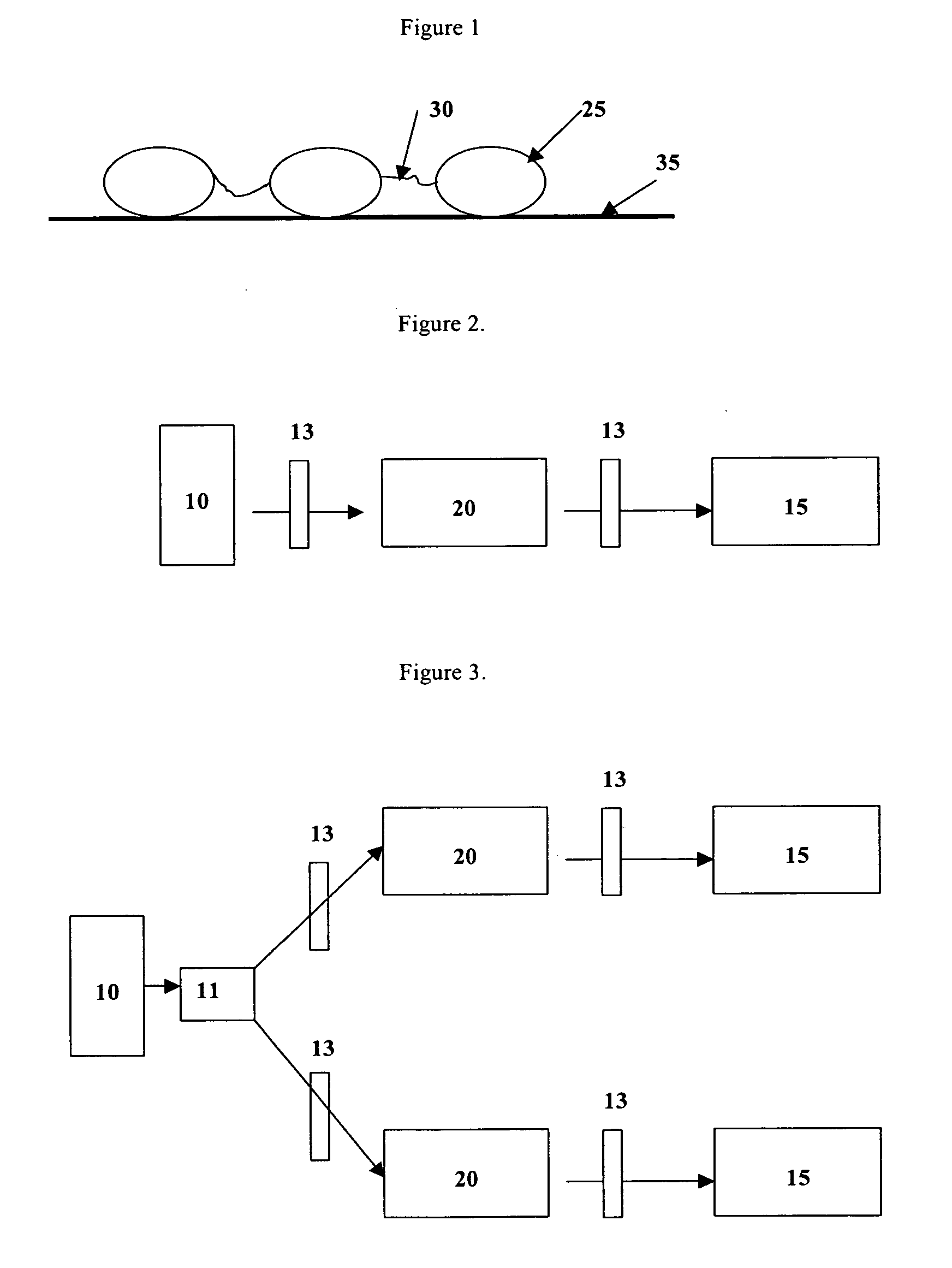
[0022] The present invention teaches a method for imaging a random or ordered array of microspheres, also referred to as “beads”, immobilized in a coating on a substrate. The microspheres are desirably formed to have a mean diameter in the range of 1 to 50 microns; more preferably in the range of 3 to 30 microns and most preferably in the range of 5 to 20 microns. It is preferred that the concentration of microspheres in the coating is in the range of 100 to a million per cm2, more preferably 1000 to 200,000 per cm2 and most preferably 10,000 to 100,000 per cm2.

[0023] Although microspheres or particles having a substantially curvilinear shape are preferred because of ease of preparation, particles of other shape such as ellipsoidal or cubic parti...


PUM

PropertyMeasurementUnit
sizeaaaaaaaaaa
mean diameteraaaaaaaaaa
colorsaaaaaaaaaa

Abstract

A method for imaging an array of microspheres. A light source, filter or combination of filters that isolate wavelength, or wavelength ranges, of light and a camera are used for detecting and quantifying the presence of biological probes that indicate the presence of specific chemical moieties within a biological system.

Description

FIELD OF THE INVENTION [0001] The present invention relates in general to molecular biological systems and more particularly to a means to simplify the detection process for colored bead random microarrays. BACKGROUND OF THE INVENTION [0002] Ever since their invention in the early 1990s (Science, 251, 767-773, 1991), high-density arrays formed by the spatially addressable synthesis of bioactive probes on a 2-dimensional solid support have greatly enhanced and simplified the process of biological research and development. The key to current microarray technology is deposition of a bioactive agent at a single spot on a microchip in a “spatially addressable” manner. [0003] Current technologies have used various approaches to fabricate microarrays. For example, U.S. Pat. No. 5,412,087, inv. McGall et al., issued on May 2, 1995 and U.S. Pat. No. 5,489,678, inv. Fodor et al., issued Feb. 6, 1996, demonstrate the use of a photolithographic process for making peptide and DNA microarrays. Th...

Claims


Application Information

Patent Timeline
Patent Type & Authority Applications(United States)
IPC IPC(8): C12Q1/68G01N33/53G06K9/00
CPCG01N2015/1465G01N15/1463
Inventor KAPLAN, MARTIN C.CHARI, KRISHNANCHEN, SAMUELVIZARD, DOUGLAS L.
Owner CARESTREAM HEALTH INC
Why Eureka
Try Eureka