Dishwasher with counter-convection air flow

Active Publication Date: 2006-10-19
ILLINOIS TOOL WORKS INC
View PDF16 Cites 25 Cited by
  • Summary
  • Abstract
  • Description
  • Claims
  • Application Information

AI Technical Summary

Benefits of technology

[0006] The present inventors have discovered that a blower directed to promote counter-convective air flow downward through an opening near the bottom of the dishwasher volume provides significantly improved dish drying with relatively low air flow. Although the inventors do not wish to be bound by a particular theory, this improvement results from a concentration of water vapor near the bottom of the dishwasher volume because of the relatively great

Problems solved by technology

One drawback to vents is that they can increase the noise emitted from the dishwasher during the washing cycle and accordingly, it is known

Method used


Image

  • Dishwasher with counter-convection air flow
  • Dishwasher with counter-convection air flow
  • Dishwasher with counter-convection air flow

Examples


Embodiment Construction

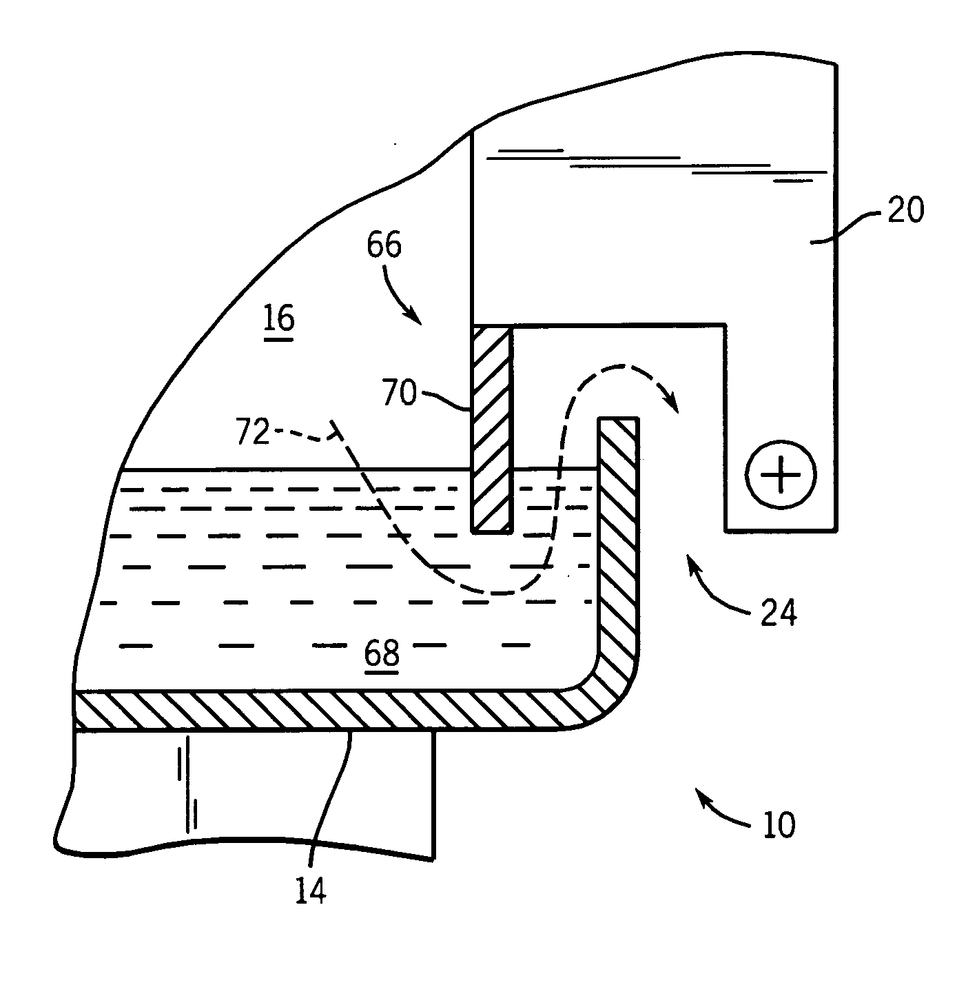
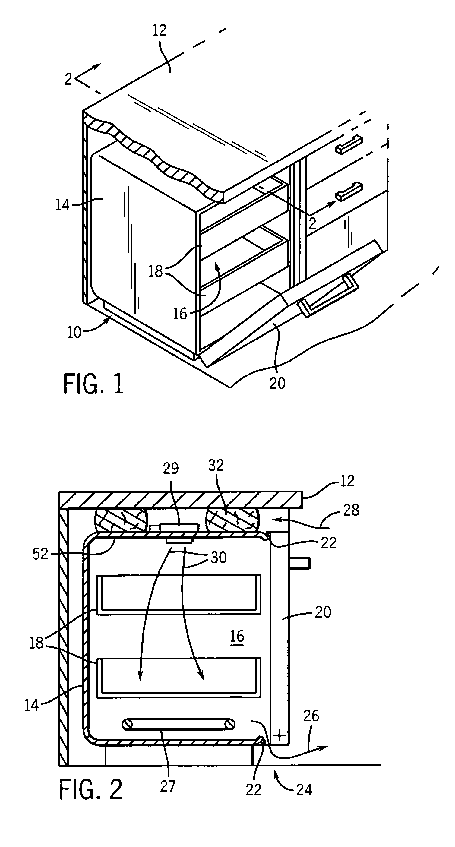
[0039] Referring now to FIG. 1, a dishwasher 10 for fitting beneath a countertop 12 may include a cabinet 14 enclosing a washing volume 16. The washing volume 16 may hold one or more racks 18 into which dishes may be loaded for cleaning as accessed through a front opening closeable by a door 20. Referring also to FIG. 2, the door 20 may be closed against door seals 22 so as to contain water within the washing volume 16 during a wash cycle.

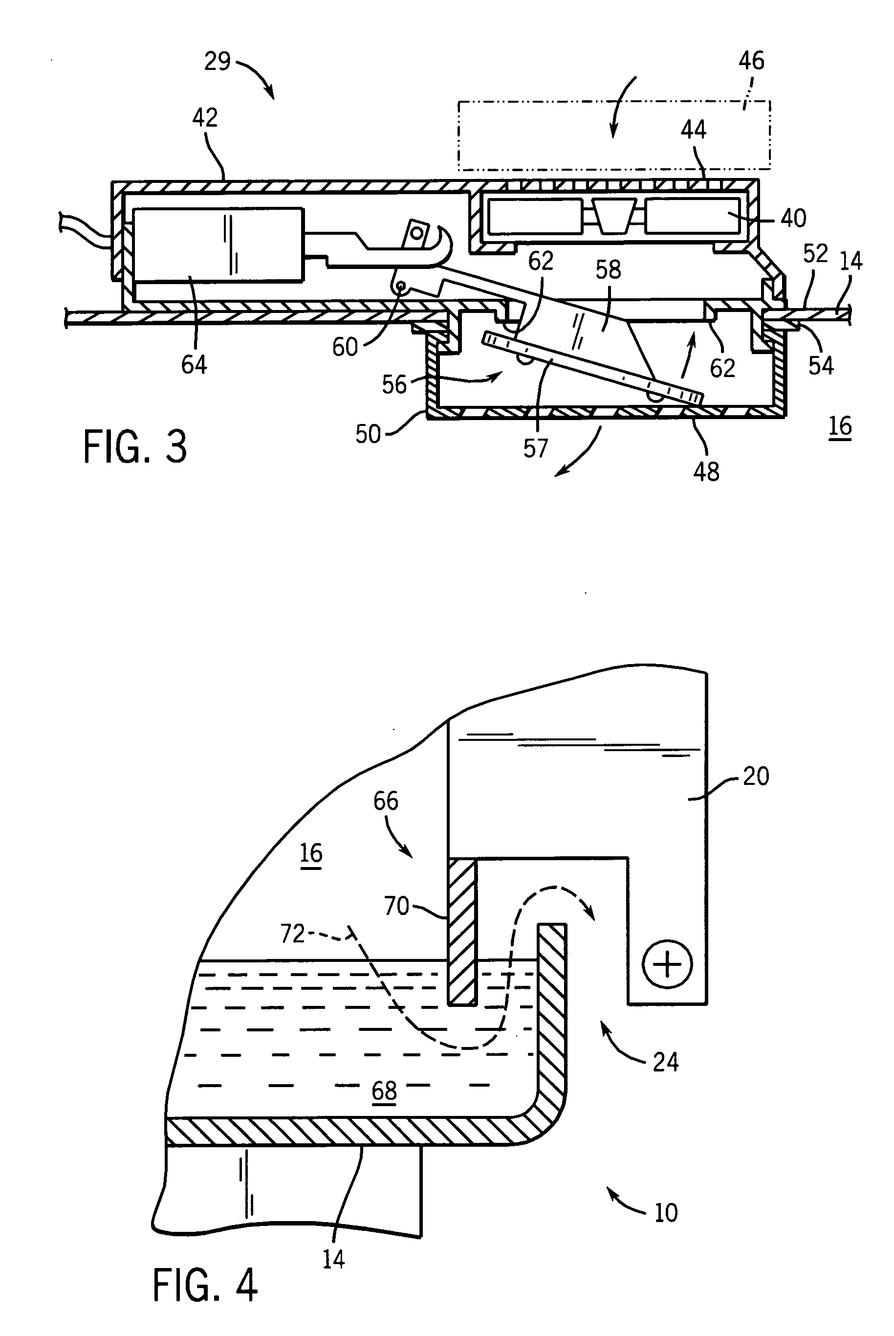
[0040] During a wash cycle, heated water is sprayed on the dishes within the washing volume 16 by stationary or movable nozzles (not shown). At the conclusion of the wash and rinse cycles as determined by a cycle timer (not shown), water is drained from the lower portion of the washing volume 16 in preparation for drying of the dishes, and in a first embodiment of the invention, a heater element 27 is activated heating the air within the washing volume 16.

[0041] At this time the cycle timer activates an air intake fan 29 positioned at a vent open...


PUM


Abstract

A dishwasher provides forced air flow in a counter-convectional direction so as to exhaust air out of a bottom portion of the washing volume in contrast to normal convective air flow.

Description

CROSS-REFERENCE TO RELATED APPLICATIONS STATEMENT REGARDING FEDERALLY SPONSORED RESEARCH OR DEVELOPMENT BACKGROUND OF THE INVENTION [0001] The present invention relates to dishwashers and in particular to dishwashers providing forced air flow during the drying cycle. [0002] Dishwashers, such as those used in a home, may provide for a washing cycle followed by a drying cycle, the latter intended to dry the washed dishes sufficiently so that they may be immediately removed from the dishwasher and stored without additional manual drying. In many cases, the drying cycle includes activation of a heating element exposed at the bottom of the washing volume to heat the dishes and create an upward convective flow of hot air. [0003] Improved drying of the dishes during the drying cycle can be obtained by venting the washing volume using vents typically located at the bottom edge of the dishwasher door and through the door near the top of the door. The vents allow cooler dry air to enter the d...

Claims


Application Information

Patent Timeline
IPC IPC(8): B08B9/20B08B7/04B08B3/00
CPCA47L15/486
Inventor STELZER, WALTER G.BREWER, MARK E.HAPKE, KENYON A.
Owner ILLINOIS TOOL WORKS INC
Why Eureka
Try Eureka