
Constant-flow uniform-temperature heating module

A technology of heating the mold and balancing the flow, which is applied in the direction of electric heating devices, metal processing equipment, manufacturing tools, etc., and can solve problems affecting the balance of heat, the stability of the hot air circulation airflow, the weak air volume in the middle area, and the influence on the stability of the airflow, etc., to achieve Improve the effective heating range, the air flow is small, and the effect of not easy to change temperature

Pending Publication Date: 2021-02-23
上海朗仕电子设备有限公司
View PDF0 Cites 0 Cited by
  • Summary
  • Abstract
  • Description
  • Claims
  • Application Information

AI Technical Summary

Problems solved by technology

[0003] At present, for the welding temperature uniformity and hot air convection stability of the customer's large product size, the heating module generally adopts the circulation mode of air suction at the front and rear ends and blowing in the middle. Because the heating module is relatively long, the air suction at the front and rear ends is concentrated at both ends , it has a greater influence on the heating of the areas near the two ends of the suction, but it has a weaker impact on the middle area, which directly affects the balance of heat in the entire heating area and the stability of the hot air circulation airflow, and it is easy to cause heat far away from the suction port. The temperature in the middle is high, and the temperature at both ends near the suction port is low, and because the air volume in the middle area is controlled weakly, it directly affects the stability of the airflow of a single heating module itself, causing airflow drift, which leads to the temperature difference between the temperature zones is not large and the temperature is shifted , nitrogen consumption and other performance problems

Method used


Image

  • Constant-flow uniform-temperature heating module

Examples


Embodiment

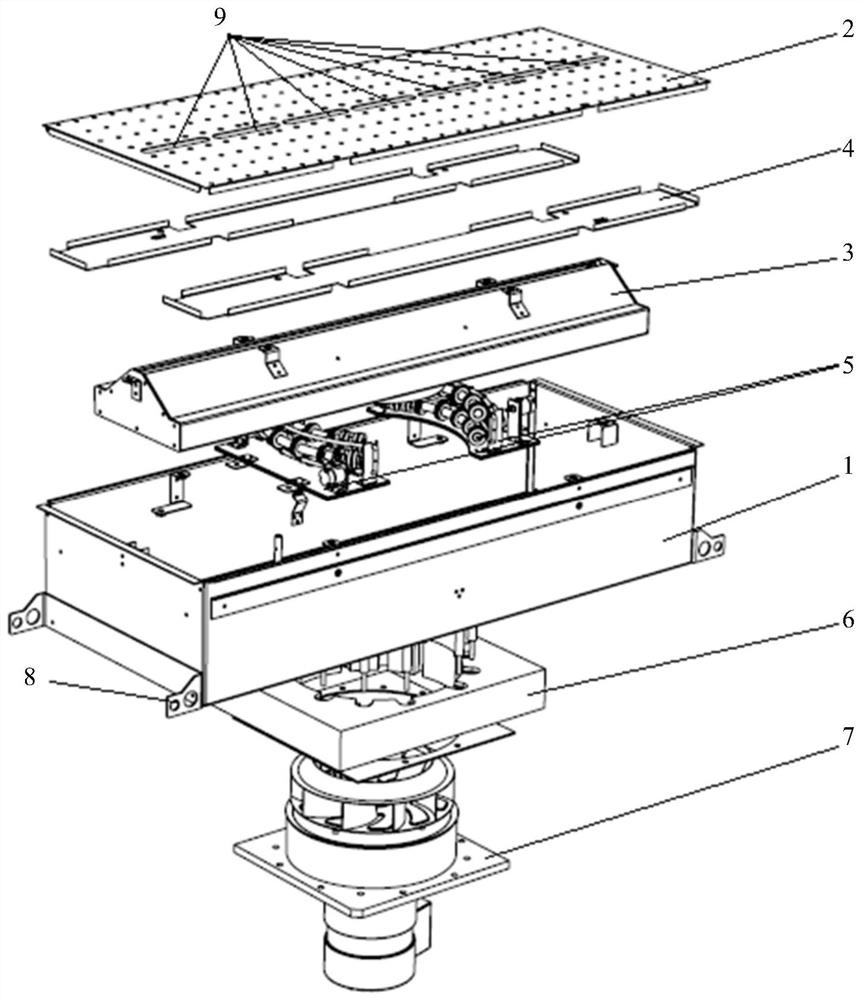
[0031] Such as figure 1 Shown is the exploded schematic view of the overall structure of the balanced flow and uniform temperature heating module of the present invention. It can be seen from the figure that the hot air perforated plate 2 is provided with a plurality of round holes arranged in an array, and the hot air perforated plate 2 blows hot air evenly across the entire surface. Product surface, heat the product. At the same time, there is a suction area in the middle of the hot air orifice plate 2, which is the suction channel of the central control suction chamber 3. The middle position below the hot air orifice plate 2 is the central control suction cavity, forming a suction cavity, and the positions on both sides are the air uniformity layer 4, which is used to balance the air flow. Below the central air suction cavity 3 is a semicircular heating wire, which is used to effectively heat the circulating air. The impeller of the blowing motor assembly 7 realizes the ga...


PUM


Abstract

The invention relates to a constant-flow uniform-temperature heating module. The constant-flow uniform-temperature heating module comprises a module outer box body, a hot air pore plate is arranged atthe bottom of the module outer box body, a center control air suction cavity is formed in the hot air pore plate, uniform air layer plates used for balancing air flow are arranged on the two sides ofthe center control air suction cavity, a heating wire module body is arranged at the top in the module outer box body, a heat insulation plate is further arranged at the top of the module outer box body, and an air blowing motor assembly is further arranged on the heat insulation plate. Compared with the prior art, the constant-flow uniform-temperature heating module has much more advantages.

Description

technical field [0001] The invention relates to the technical field of reflow soldering, in particular to a heating module with balanced current and uniform temperature. Background technique [0002] As we all know, in the production of SMT (Surface Mounting Technology), various electrical components are combined with the PCB board through the melting and solidification of solder paste, and it is very important to control the welding process during the entire heating and cooling stages of welding. Especially during the heating phase. With the development of surface mount technology and technology becoming more and more mature, customers continue to put forward new requirements for reflow ovens. With the development of 5G technology, customers' products are getting bigger and bigger, and the high quality of reflow ovens The welding requirements of components are more stringent, and new requirements are put forward for equipment production capacity, energy saving and equipmen...

Claims


Application Information

Patent Timeline
Patent Type & Authority Applications(China)
IPC IPC(8): B23K1/08B23K3/047
CPCB23K1/08B23K3/0478
Inventor 卢明马雪峰詹姆斯·内维尔大卫·海乐
Owner 上海朗仕电子设备有限公司
Learn More