Eureka AIR delivers breakthrough ideas for toughest innovation challenges, trusted by R&D personnel around the world.

Windscreen wiper device in particular for a motor vehicle

Inactive Publication Date: 2006-10-19
ROBERT BOSCH GMBH
View PDF5 Cites 0 Cited by
  • Summary
  • Abstract
  • Description
  • Claims
  • Application Information

AI Technical Summary

Benefits of technology

[0005] The windshield wiper device in accordance with the invention has the advantage that because of the arrangement of a connecting element on the decoupling element, a simple connection is available to fix the decoupling element on the windshield wiper device. This makes simple assembly of the windshield wiper device possible, whereby particularly in series manufacturing a considerable cost advantage is achieved.
[0008] In a simple and cost-effective embodiment, the connecting element is embodied as a speed nut.
[0009] The damping section of the decoupling element is advantageously embodied of an elastic material in order to effectively dampen vibrations of the windshield wiper device and prevent transmission to the vehicle body.
[0010] In addition, it is also considered advantageous if the windshield wiper device has a drive unit with a gearbox housing and the decoupling element acts on the gearbox housing so that the damping via the damping section is arranged as close as possible to the source of emission, i.e., the drive unit.
[0011] Because of the three decoupling elements, the fastening is precisely determined statically and offers optimal hold on the body of the motor vehicle.
[0013] In a simple design, the fixing section features an internal or external screw thread for a screwed connection to the motor vehicle.

Problems solved by technology

However, these types of decoupling elements are very large and must be threaded in during manufacturing in a relatively expensive manner.
In addition, these elements are only conditionally suitable for a wiper direct drive, in which the wiper arm is connected to the wiper blade directly with the driven shaft of a drive device—without a thrust rod gear.
In addition, most of the time commercially available decoupling elements are provided with screwed connections, which cannot be realized in diecast parts without an additional work cycle, however.

Method used


Image

  • Windscreen wiper device in particular for a motor vehicle
  • Windscreen wiper device in particular for a motor vehicle

Examples


Embodiment Construction

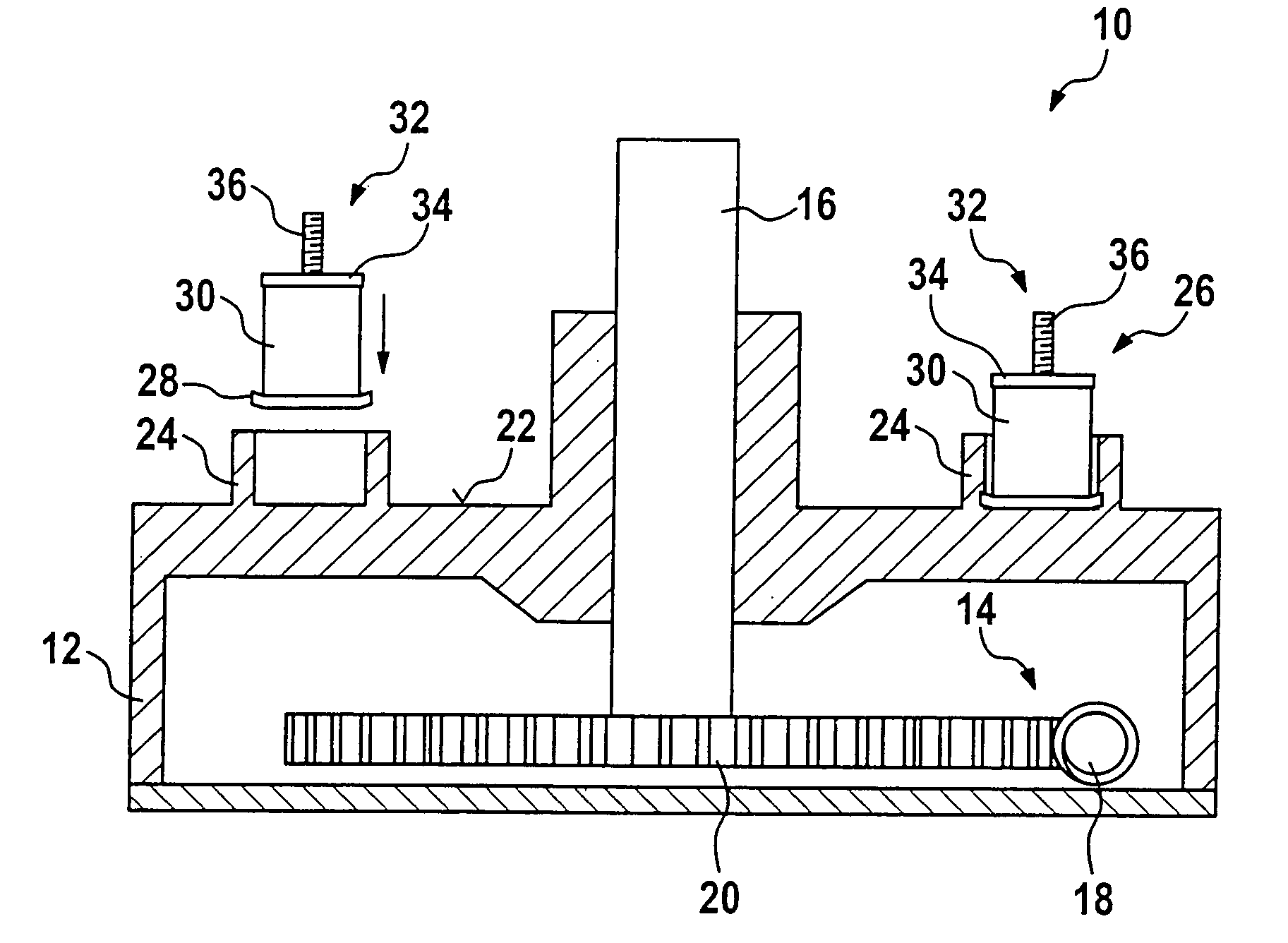
[0019]FIG. 1 shows a schematic cross-section depiction of a windshield wiper device 10 in accordance with the invention. The windshield wiper device 10 essentially comprises a drive unit, which is not depicted here for reasons of clarity, as well as gearbox housing 12 surrounding a gear 14 with a driven shaft 16, which projects out of the gearbox housing 12. The gear 14 includes at least one worm 18, which meshes with a worm wheel 20 that is connected in its rotational center to the driven shaft 16 so that it is resistant to torsion.

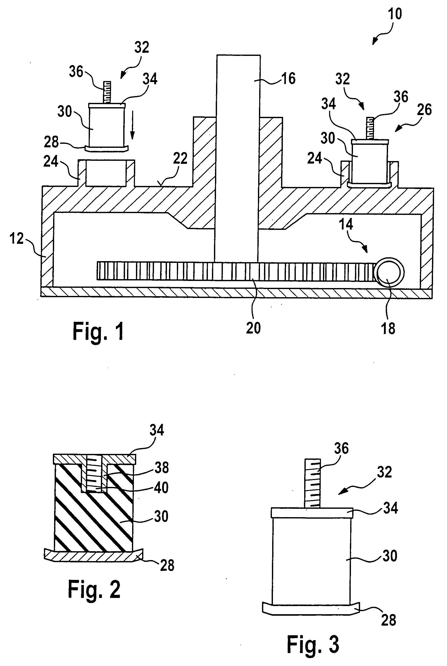
[0020] On the outside 22 of the gear housing 12 facing the driven shaft 16, said housing has three receptacles 24, which are embodied as hollow cylindrical elevations. A decoupling element 26 is placed in each of the receptacles 24. Naturally, only two receptacles 24, but also four or more receptacles 24 can be provided as an alternative.

[0021] The decoupling element 26 essentially has three sections. The first section is comprised of a connecting elem...


PUM

PropertyMeasurementUnit
Speedaaaaaaaaaa
Elasticityaaaaaaaaaa

Abstract

A windshield wiper device (10), in particular for a motor vehicle, is disclosed, comprising a fixing section (32) for fixing the windshield wiper device (10) in or on the motor vehicle, which features a decoupling element (30), whereby a connecting element (28) is provided on the decoupling element (30) so that the decoupling element (30) is fixed to the windshield wiper device (10) by means of a connection process.

Description

BACKGROUND OF THE INVENTION [0001] The invention relates to a windshield wiper device, in particular for a motor vehicle. [0002] Numerous windshield wiper devices for motor vehicles are already known, which feature a decoupling element that serves to fix the windshield wiper device in or on the motor vehicle. For example, a windshield wiper device is known from DE-A-101 14 033, in which an annular decoupling element is provided with a screw that is used for fixing to the body of the motor vehicle. [0003] However, these types of decoupling elements are very large and must be threaded in during manufacturing in a relatively expensive manner. In addition, these elements are only conditionally suitable for a wiper direct drive, in which the wiper arm is connected to the wiper blade directly with the driven shaft of a drive device—without a thrust rod gear. In the case of these types of windshield wiper devices, the drive unit essentially includes only one electric motor with a step-down...

Claims


Application Information

Patent Timeline
IPC IPC(8): B60S1/06B60S1/04F16F1/373F16F1/52F16F15/08
CPCB60S1/0438B60S1/0444F16F15/08F16F1/373F16F1/52B60S1/0447B60S1/04F16F1/36F16F1/42
Inventor STUBNER, ARMIN
Owner ROBERT BOSCH GMBH
Why Eureka
Eureka Blog
Learn More