

Structure of automotive alternator
- Summary
- Abstract
- Description
- Claims
- Application Information
AI Technical Summary
Benefits of technology
Problems solved by technology
Method used
Image

Examples
first embodiment
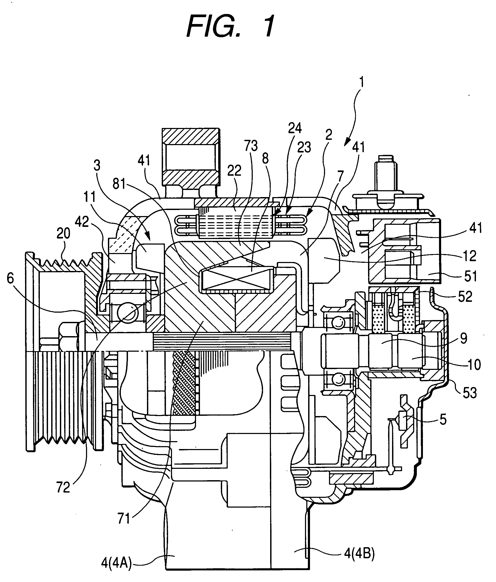
[0037] Referring to the drawings, wherein like reference numbers refer to like parts in several views, particularly to FIG. 1, there is shown an AC generator or alternator 1 for automotive vehicles according to the invention.
[0038] The alternator 1 consists essentially of a stator 2, a rotor 3, a frame 4, and a rectifier device 5.
[0039] The stator 2 includes a stator core 22, a stator winding 23, and insulators 24. The stator winding 23 is made of a plurality of sequentially-joined conductor segments disposed in 96 slots 25 formed in the stator core 22. The insulators 24 are disposed in the stator core 22 to insulate the stator core 22 electrically from the stator winding 23. The stator core 22 is made of a lamination of thin steel plates. The stator winding 23 is made up of two types of portions: one being disposed in the slots 25 of the stator core 22 (will be referred to as in-slot portions below), and the other extending in an axial direction of the stator core 22 outside ends ...
third embodiment
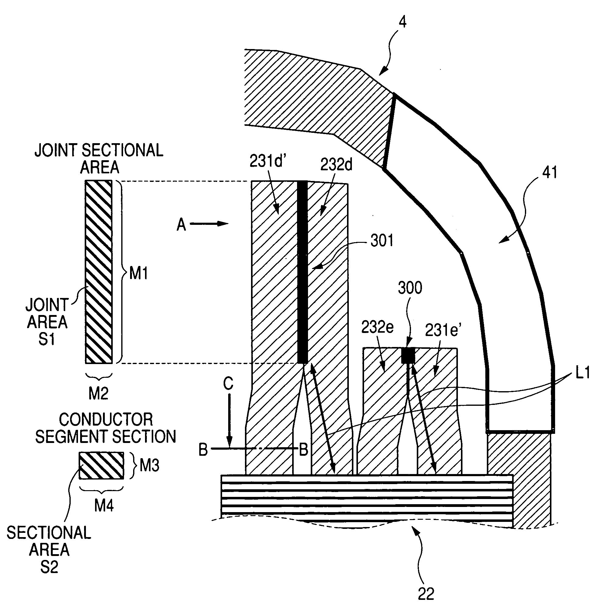
[0077]FIG. 9 shows highlights of an alternator according to the invention.
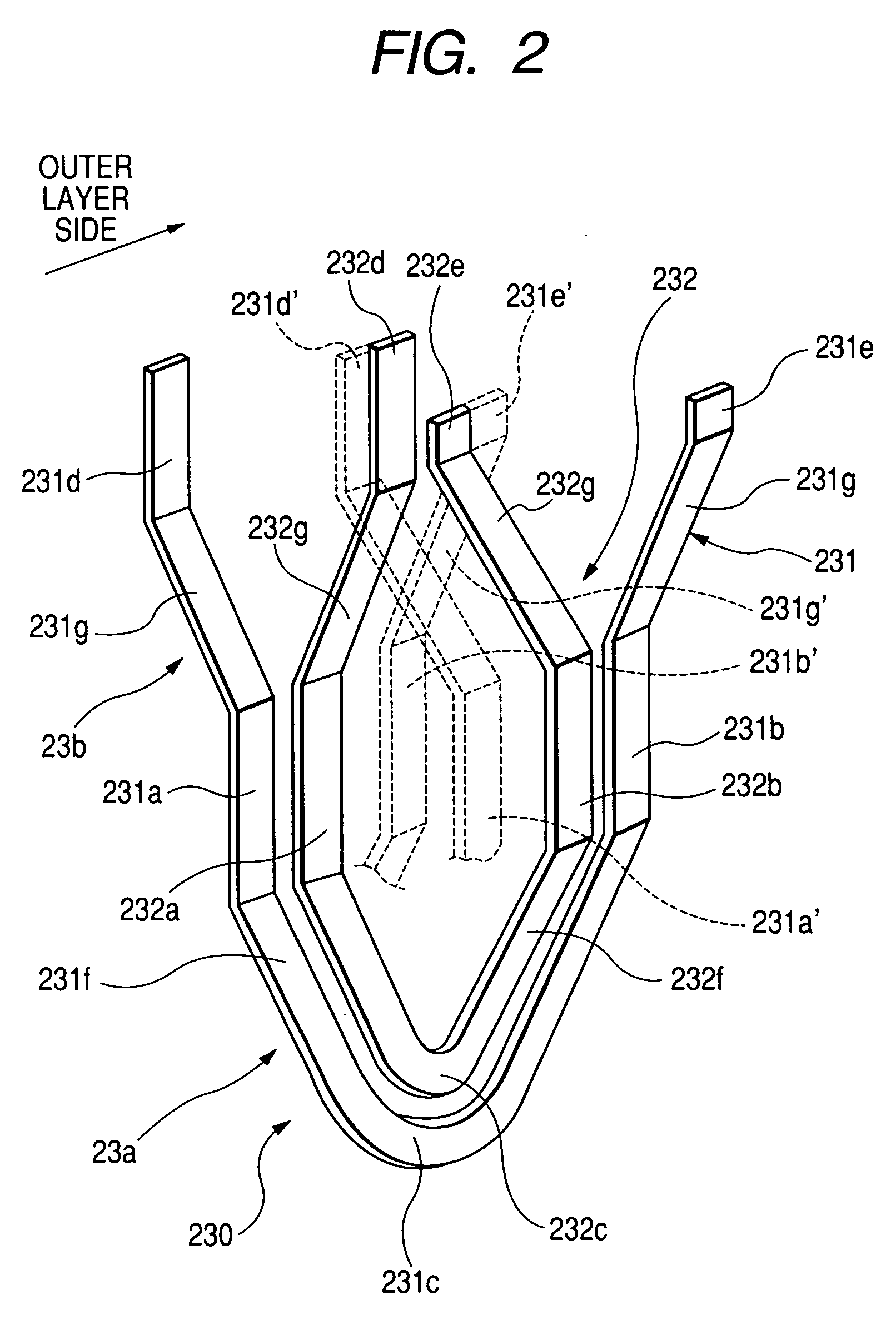
[0078] The innermost straight end portion 231d′ of each of the large-sized conductor segments 231 and the inner intermediate straight end portion 232d of each of the small-sized conductor segments 232 are longer than the other straight end portions 232e and 231e′. Other arrangements are identical, and explanation thereof in detail will be omitted here.
[0079] Portions of the side walls of the straight end portions 231d′ and 232d which are at a preselected distance from the tips thereof are welded together to form a joint 305.
[0080] Portions of the conductor segments 230 between the tips of the straight end portions 231d′ and 232d and the joint 305 function as a radiator fin. The induced current, as produced in the conductor segments 230, flows through the joint 305 without passing through the radiator fin, thus resulting in no increase in electrical resistance of the conductor segments 230 to the flow of the ...
fourth embodiment
[0084] FIGS. 10(a), 10(b), and 10(c) show highlights of an alternator according to the invention which is different from those in the above embodiment in that the ends of the conductor segments 230 are joined using a separate joining member 2310.
[0085] The joining member 2310 is, as illustrated in FIG. 10(c), of a T-shape and formed by Fe-metallic plate plated with Cu which is high in thermal conductivity or alternatively Ni which is easy to weld. The joining member 2310 is made up of a rectangular strip 2311 functioning as a radiator fin and an elastically deformable strip 2312 extending perpendicular to the length of the rectangular strip 2311. The thickness and profile of the joining member 2310 are so predetermined as to establish required heat dissipating ability.
[0086] Joining of the straight end portions 231d′ and 232d is achieved by wrapping the elastically deformable strip 2312 about the straight end portions 231d′ and 232d and crimp it tightly, as illustrated in FIGS. 10(...
PUM
 Abstract
Description
Claims
Application Information