
Sb-Te base alloy sinter sputtering target

a technology of te base alloy and sputtering target, which is applied in the manufacture of optical record carriers, diaphragms, and record information storage. it can solve the problems of deteriorating the quality of the thin film as the recording medium, cracks or fractures in the target, and affecting the quality of the recording medium. it achieves the effect of increasing the electrical resistance of the phase change recording layer and effectively inhibiting

Active Publication Date: 2014-11-11
JX NIPPON MINING & METALS CORP
View PDF41 Cites 4 Cited by
  • Summary
  • Abstract
  • Description
  • Claims
  • Application Information

AI Technical Summary

Benefits of technology

[0025]The present invention seeks to increase the electrical resistance of the phase change recording layer by adding carbon or boron to the Sb—Te base alloy sinter target for forming the phase change recording layer, and provides a target capable of overcoming the various problems described above; namely, the target capable of effectively inhibiting the generation of particles, abnormal discharge and nodules and the generation of cracks and fractions in the target during the sputtering process. In particular, the present invention provides an Sb—Te base alloy sinter sputtering target for forming a phase change recording layer formed from Ag—In—Sb—Te alloy or Ge—Sb—Te alloy.
[0033]With the Sb—Te base alloy sintered compact of the present invention, since it is possible to inhibit the coarsening of the added carbon or boron which is nonmetal, it yields a superior effect of preventing abnormal discharge originated from such carbon or boron and inhibiting the generation of particles caused by arcing. Moreover, although machining such as cutting work is performed at the stage of finishing the target, if there is coarsened carbon or boron, it might cause the generation of cracks and the like, and the generation of particles originated from these cracks could also be considered. The present invention is able to achieve a considerable effect of preventing the foregoing problems from occurring.

Problems solved by technology

When forming a film formed from an Sb—Te base alloy material for use in a phase change recording film, specific problems arise including the generation of particles during sputtering or the generation of nodules (projections) that cause abnormal discharges (micro arcing) or the formation of clustered thin films (i.e., thin films in which nodules are solidified and attached), the generation of cracks or fractures in the target during the sputtering process, and the absorption of large amounts of gas components such as oxygen during the production process of sintered powder for use in a target.
These problems encountered in targets and during the sputtering process will become a significant cause of deteriorating the quality of the thin film as the recording medium.
It is known that the foregoing problems are largely affected by the grain size of the sintering powder or the target structure or shape.
Nevertheless, since the target obtained by sintering is unable to retain sufficient characteristics upon producing an Sb—Te base alloy sputtering target for forming a phase change recording layer, it was not conventionally possible to avoid the generation of particles, abnormal discharge and nodules during the sputtering process, the generation of cracks or fractures in the target during the sputtering process, and the inclusion of large amounts of gas components such as oxygen contained in the target.
It is not possible to obtain a sufficient strength of the target, and it cannot be said that the miniaturization and homogenization of the target structure have been achieved.
In addition, the tolerable oxygen content is high, and there is a problem in that it is insufficient as an Sb—Te base sputtering target for forming a phase change recording layer.
However, since carbon powder is nonmetal, if carbon is mixed into a conventional Sb—Te base alloy sputtering target, it rather becomes an addition of foreign matter.
There has been a problem that carbon is not necessarily a favorable additive because this easily generates abnormal discharge during the sputtering process, the generation of particles increases, and cracks sometimes occur in the target.[Patent Document 1] Japanese Patent Laid-Open Publication No. 2000-265262[Patent Document 2] Japanese Patent Laid-Open Publication No. 2001-98366[Patent Document 3] Japanese Patent Laid-Open Publication No. 2001-123266[Patent Document 4] Japanese Patent Laid-Open Publication No.

Method used


Image

  • Sb-Te base alloy sinter sputtering target
  • Sb-Te base alloy sinter sputtering target

Examples


example 1

[0059]Ag, In, Sb and Te powder raw materials each having a purity of 4N or higher excluding gas components were mixed and synthesized to achieve an Ag5In5Sb70Te20 alloy, and this was subject to machine pulverization in an inert atmosphere. Consequently, as shown in Table 1, powder having an average grain size (X) of 8.0 μm was obtained.

[0060]Subsequently, this was divided into the four types of (1), (2), (3) and (4), and each of the four types of powders was mixed with 5 at % of the carbon powders having the average particle sizes (Y) of 30 nm, 50 nm, 7 nm and 750 nm respectively, as shown in Table 1, and then hot pressed. Each of the obtained sintered compact was subject to machining, and additionally subject to polishing to obtain an Ag5In5Sb70Te20 alloy target containing a prescribed amount of carbon.

[0061]The obtained alloy target comprised a structure in which the Sb—Te base alloy particles were surrounded by fine carbon particles. Table 1 shows the ratio of Y / X and the density...

example 2

[0066]Ge22.2Sb22.2Te55.6 alloy raw material was injected at 780° C. with a gas atomization device using argon (100 kgf / cm2) as the injection gas to prepare atomized powder. Consequently, fair spherical powder was obtained.

[0067]From this gas atomized powder, as shown in Table 2, powder having an average grain size (X) of 32.0 μm was obtained. Subsequently, this was divided into the four types of (1), (2), (3) and (4), and each of the four types of powders was mixed with 5 at % of the carbon powders having the average particle sizes (Y) of 30 nm, 50 nm, 7 nm and 750 nm respectively, as shown in Table 2, and then hot pressed.

[0068]Each of the obtained sintered compact was subject to machining, and additionally subject to polishing to obtain a Ge22.2Sb22.2Te55.6 alloy target containing a prescribed amount of carbon. Table 2 shows the ratio of Y / X and the density.

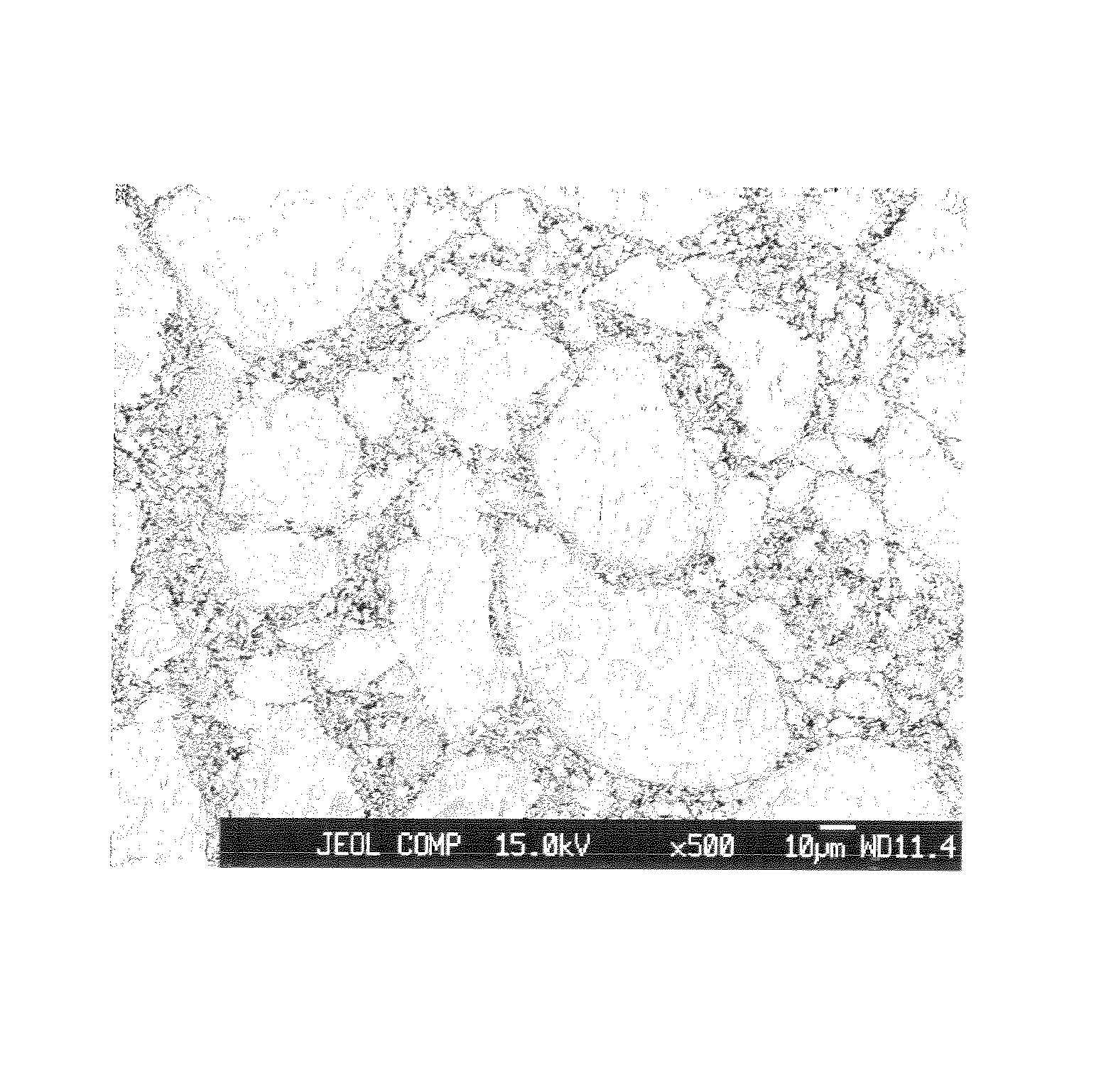
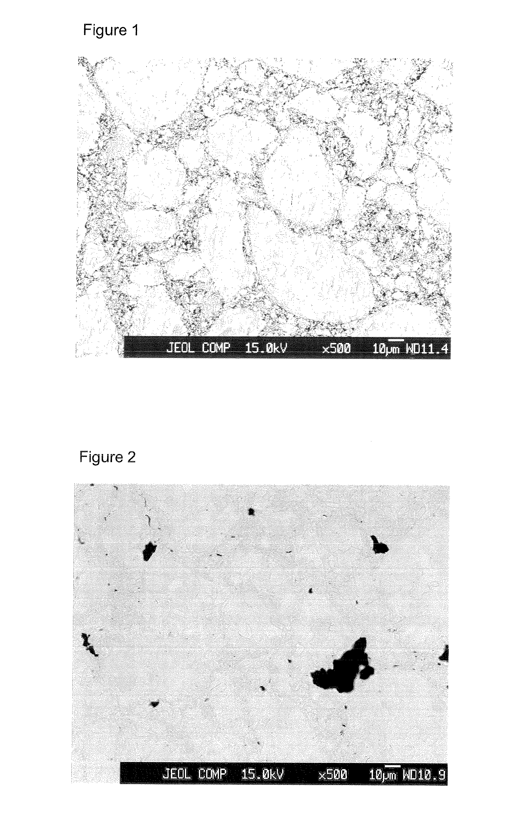
[0069]The SEM photograph of the obtained target surface is shown in FIG. 1. As shown in FIG. 1, no defects such as cracks can...


PUM

PropertyMeasurementUnit
mean diameteraaaaaaaaaa
diameteraaaaaaaaaa

Abstract

Provided is an Sb—Te base alloy sinter sputtering target having Sb and Te as its primary component and comprising a structure in which Sb—Te base alloy particles are surrounded by fine carbon or boron particles; wherein, if the mean diameter of the Sb—Te base alloy particles is X and the particle size of carbon or boron is Y, Y / X is within the range of 1 / 10 to 1 / 10000. The present invention seeks to improve the Sb—Te base alloy sputtering target structure, inhibit the generation of cracks in the sintered target, and prevent the generation of arcing during the sputtering process.

Description

BACKGROUND OF THE INVENTION[0001]The present invention relates to an Sb—Te base alloy sinter sputtering target containing carbon or boron and capable of effectively inhibiting the generation of particles.[0002]In recent years, a thin film formed from an Sb—Te base material is being used as a phase change recording material; that is, as a medium for recording information by using phase transformation. As a method of forming this thin film formed from the Sb—Te base alloy material, it is standard to use a means generally referred to as a physical vapor deposition method such as the vacuum deposition method or the sputtering method. In particular, the thin film is often formed using the magnetron sputtering method from the perspective of operability and film stability.[0003]Formation of films by way of the sputtering method is performed by physically colliding positive ions such as Ar ions to a target disposed on a cathode, using that collision energy to discharge materials configuring...

Claims


Application Information

Patent Timeline
Patent Type & Authority Patents(United States)
IPC IPC(8): C25B13/00C23C14/34B22F1/00C23C14/00C22C12/00G11B7/26B22F3/00C25B9/00C22C1/00C25B11/00C22C28/00C23C14/06C22C1/04C22C1/05G11B7/243G11B7/2433
CPCB22F3/14G11B7/266C22C12/00B22F2998/10C23C14/0623C22C1/05C22C28/00C23C14/3414B22F9/082B22F3/10B22F9/08
Inventor YAHAGI, MASATAKATAKAHASHI, HIDEYUKIAJIMA, HIROHISA
Owner JX NIPPON MINING & METALS CORP
Learn More