Apparatus and method for providing snapshot action thermal infrared imaging within automated process control article inspection applications

a technology of thermal infrared imaging and automated process control, which is applied in the direction of optical radiation measurement, instruments, television systems, etc., can solve the problems of inability to implement the state-of-the-art microbolometer device in a manner, the cost of indium antimonide-based cameras is high, and the thermal ir camera commercial deployment is difficult. , to achieve the effect of robust structural integrity inspection capability, low cost and high sensitivity

Active Publication Date: 2006-10-19
PRESSCO TECH INC
View PDF29 Cites 24 Cited by
  • Summary
  • Abstract
  • Description
  • Claims
  • Application Information

AI Technical Summary

Benefits of technology

[0014] An advantage of the present invention is the ability to provide low-cost, on-line surface and sub-surface inspection of articles within a portion of the thermal IR portion of the electromagnetic spectrum (2 to 5 um).
[0015] Another advantage of the present invention is the ability to provide a very robust structural integrity inspection capability for articles and items which are generally transparent within the visible and near IR portion of the electromagnetic spectrum.
[0016] Another advantage of the present invention is the ability to provide high sensitivity, high speed, infrared imaging without implementing

Problems solved by technology

There are, however, several drawbacks to using this type of camera in machine vision applications and thus commercial deployment of thermal IR cameras in machine vision applications has been difficult.
These drawbacks include the high-price and lack of ruggedness associated with a Stirling-cycle cooled, Indium Antimonide-based camera of this type.
Despite the body of knowledge that is available, none of the state-of-the-art microbolometer devices have been implemented in a manner that addresses the specific pixel-level functionality required for snapshot mode image acquisition.
In addition, the

Method used


Image

  • Apparatus and method for providing snapshot action thermal infrared imaging within automated process control article inspection applications
  • Apparatus and method for providing snapshot action thermal infrared imaging within automated process control article inspection applications
  • Apparatus and method for providing snapshot action thermal infrared imaging within automated process control article inspection applications

Examples


Embodiment Construction

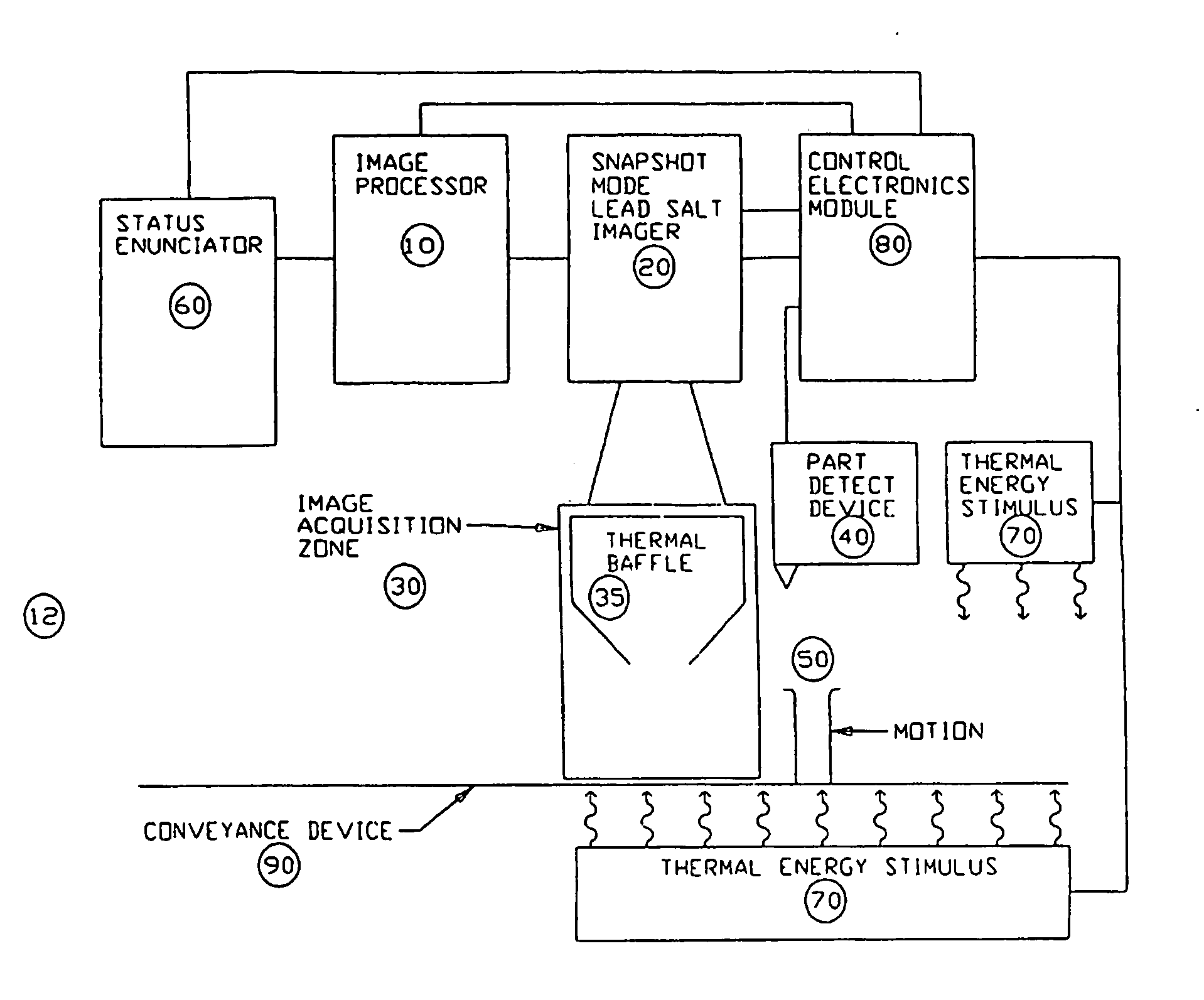
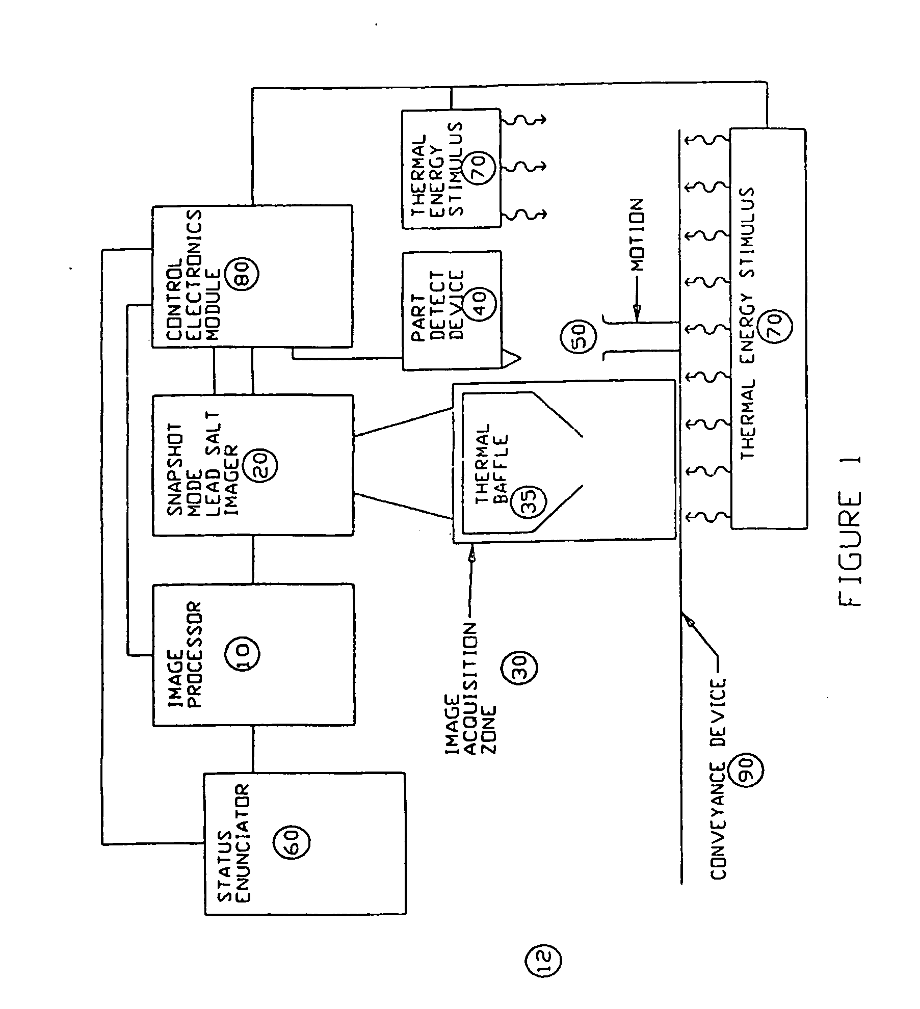
[0024] Referring now to the drawings wherein the showings are for purposes of illustrating preferred embodiments of the invention only and not for purposes of limiting same, FIG. 1 provides a view of an overall preferred system 12 according to the present invention. As shown, an imager, preferably a snapshot mode lead salt imager, 20 is positioned to obtain infrared image data of objects or articles 50 under test as such objects move under the influence of a conveyance device 90 through a designated image acquisition zone 30. A control electronics module 80 acts to coordinate the operations of the functional components contained within the system such as an imager processor 10, a status enunciator 60, a thermal energy stimulus 70, the imager 20, and a part detection device 40. The part detection device 40 detects the presence of an object, or article, 50 as it moves toward the image acquisition zone 30.

[0025] In one preferred embodiment, the thermal energy stimulus 70 is provided t...


PUM


Abstract

This application relates to an apparatus and method for providing snapshot action thermal infrared imaging within automated process control article inspection applications. More specifically, it pertains to the use of snapshot mode lead salt area-array imaging sensors (20) as the imaging front-end in high-speed machine vision inspection systems (12). the relatively low-cost, good measurement sensitivity at temperatures consistent with thermo-electric cooling means, and the ability to be operated in snapshot mode enables lead salt-based image acquisition sensors (20) to be used in a variety of automated process control and article inspection applications.

Description

[0001] This application is based on and claims priority to U.S. Provisional Patent Application No. 60 / 292,421, filed May 21, 2001.BACKGROUND OF THE INVENTION [0002] This application relates to an apparatus and method for providing snapshot action thermal infrared imaging within automated process control article inspection applications. More specifically, it pertains to the use of snapshot mode lead salt area-array imaging sensors as the imaging front-end in high-speed machine vision inspection systems. The use of lead salt-based image acquisition sensors in a snapshot or stop-action mode allows for a wide variety of automated process control or article inspection applications. [0003] While the invention is particularly directed to the art of high-speed automated product inspection, and will be thus described with specific reference thereto, it will be appreciated that the invention may have usefulness in other fields and applications. For example, the invention may be used in other ...

Claims


Application Information

Patent Timeline
IPC IPC(8): H04N7/18H04N5/33G01N25/72
CPCG01J2005/0077G01N21/88G01N21/89H04N5/33G01N2021/845H01L27/1467G01N25/72
Inventor COCHRAN, DONW
Owner PRESSCO TECH INC
Why Eureka
Try Eureka