Optical module

Inactive Publication Date: 2006-10-19
HAMAMATSU PHOTONICS KK
View PDF10 Cites 8 Cited by
  • Summary
  • Abstract
  • Description
  • Claims
  • Application Information

AI Technical Summary

Benefits of technology

[0017] Also, the second alignment portion may be formed substantially parallel to the fixing groove. In this case, the second alignment portion and the fixing groove can be formed readily while being aligned with respect to each other.

Problems solved by technology

When such a step of mounting the optical fiber is carried out at an early stage of assembling the entire optical module, handling an

Method used


Image

  • Optical module
  • Optical module
  • Optical module

Examples


Embodiment Construction

[0028] Preferred embodiments of the present invention's optical module shall now be described along with the drawings. In the description of the drawings, the same elements shall be provided with the same symbols and redundant description shall be omitted. The dimensional proportions of the drawings do not necessarily match those of the descriptions.

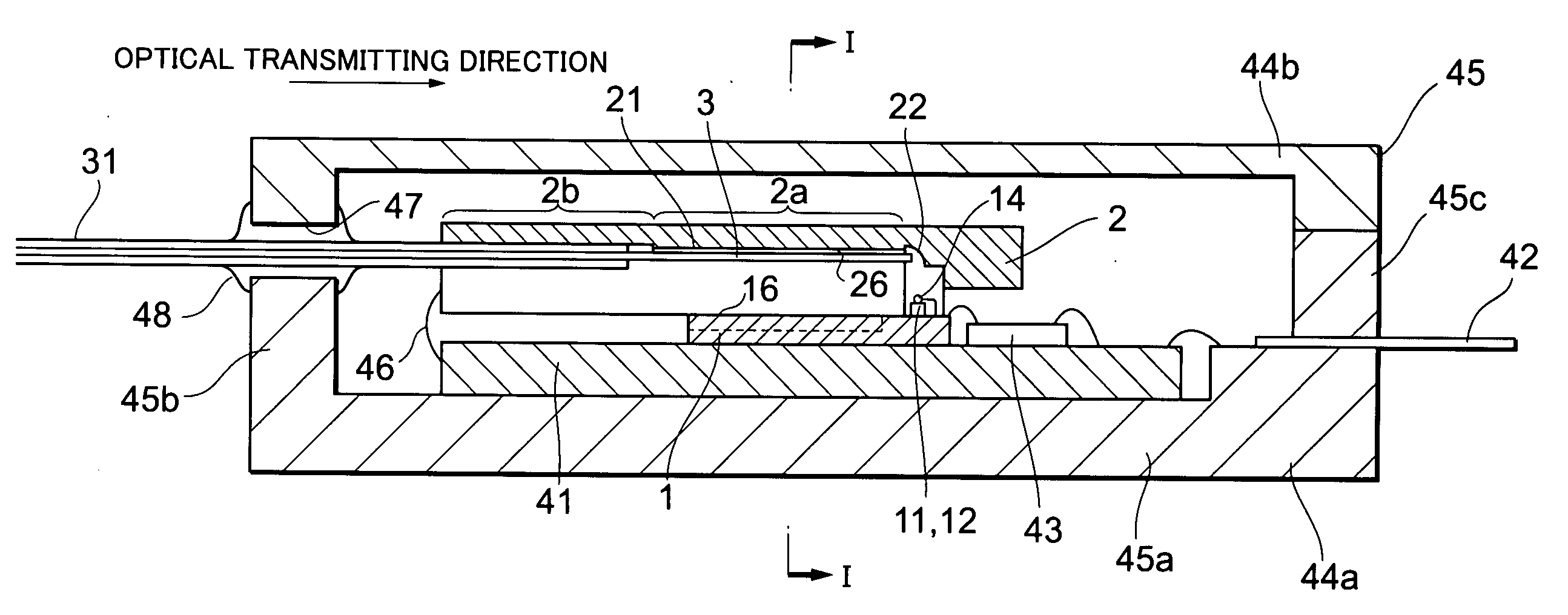
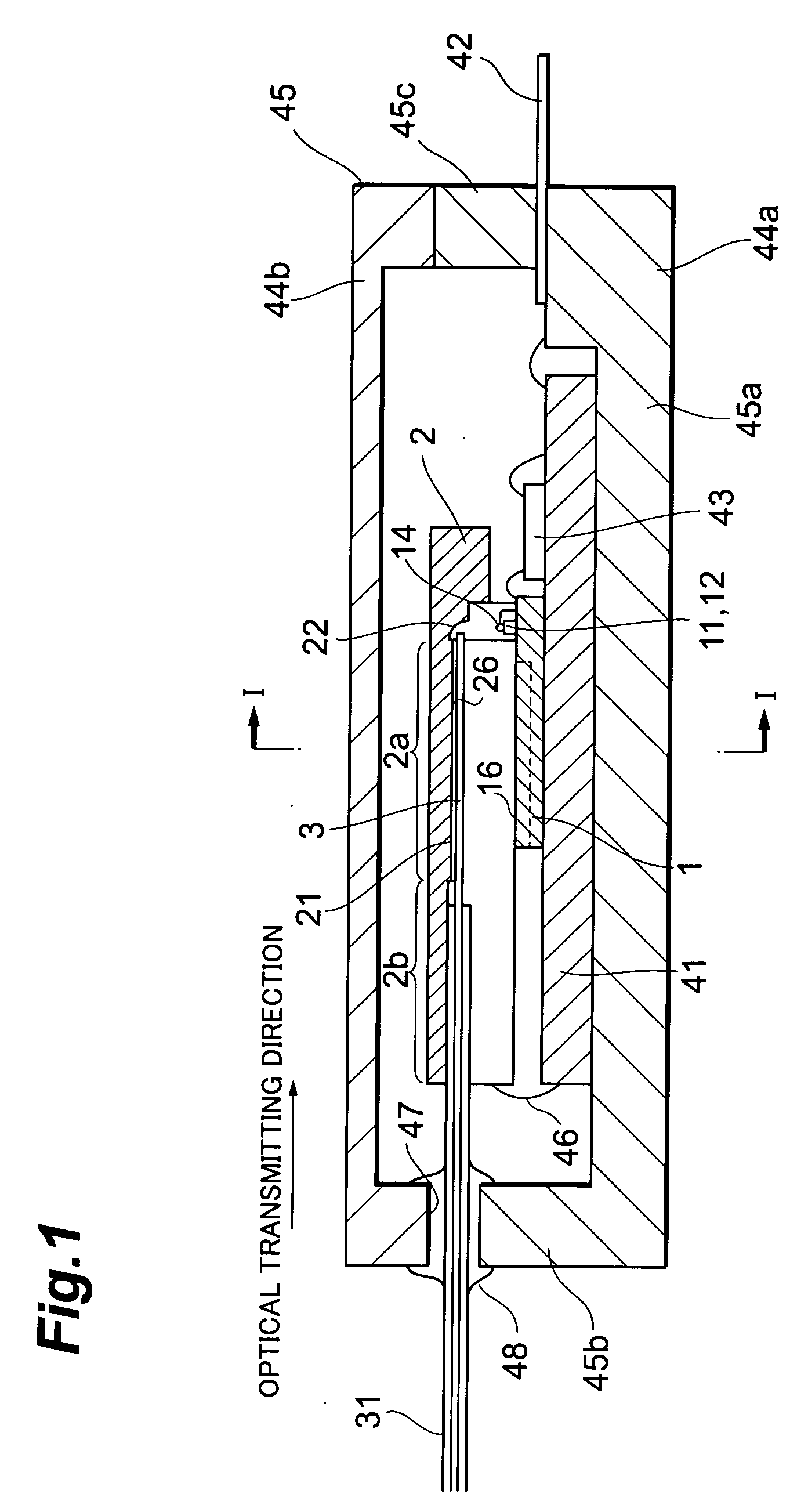
[0029]FIG. 1 is a sectional side view showing the arrangement of an embodiment of the present invention's optical module. The arrangement of this embodiment's optical module shall be described in outline using FIG. 1. This optical module is an optical module for optical transmission or optical receiving that transmits or receives optical signals in parallel and has N (where N is a natural number) optical fibers optically connected with N optical semiconductor elements. With the embodiment to be described below, N=4. Also, FIG. 1 shows the cross-sectional view in the plane containing the optical axes of one set among four sets of the opt...


PUM


Abstract

An optical module comprises: a sub-mount 1, having four photodiodes 12 and two guide grooves 10 disposed on an optical element mounting surface 16; a fiber fixing member 2, having four V-grooves 21, four concave mirrors 22, and two guide rails 20 disposed on an optical fiber fixing surface 26; and four optical fibers 3, fixed to the fiber fixing member 2. With this optical module, the sub-mount 1 and fiber fixing member 2 are aligned and fixed by the fitting together of the guide grooves 10 and guide rails 20. A passive alignment type optical module that enables mass production and cost reduction is thus realized.

Description

TECHNICAL FIELD [0001] The present invention relates to an optical module, wherein an optical fiber and an optical semiconductor element are connected optically. BACKGROUND ART [0002] With the improvement and expansion of backbone infrastructure in recent years, the focus of attention in the optical communication market is being directed to the furnishing of user line equipment and equipment for connecting user lines with the backbone. Specifically, enhancement of metro area networks, access systems, and school and company LANs and higher speeds and greater capacities in provider's servers and routers are being desired. [0003] In particular, optical connections in a school or company LAN or among servers, routers, etc., within a provider are called VSR (Very Short Reach) or interconnections. Although being short in distance, signal transmissions of high speed and high volume are desired of such optical connections. Since low cost is also desired, expensive equipment, such as that re...

Claims


Application Information

Patent Timeline
IPC IPC(8): G02B6/36G02B6/42H01L31/02H01L31/0232H01L33/58H01L33/60H01S5/026
CPCG02B6/4201G02B6/4214G02B6/423G02B6/4249H01L2224/48091H01L2224/45144H01L2924/00014H01L2924/00G02B6/4243G02B6/38
Inventor HOSHINO, YASUJIIIDA, TAKASHIWARASHINA, YOSHIHISATABATA, KEI
Owner HAMAMATSU PHOTONICS KK
Why Eureka
Try Eureka