In-mold metallized polymer components and method of manufacturing same

Inactive Publication Date: 2006-10-19
TICONA POLYMERS INC
View PDF4 Cites 2 Cited by
  • Summary
  • Abstract
  • Description
  • Claims
  • Application Information

AI Technical Summary

Benefits of technology

[0009] Generally, a metal alloy and a polymer resin are selected so that they are carefully matched with respect to their relative melting points and in order to insure that the polymer and metal are not miscible. It is particularly important within the scope of the present invention that the melting point of the metallic alloy be tailored to fall towards the upper end of the desired molding range of the base polymer resin and above the temperature at which the resin is typically compounded. Further, it is also important that the melting point of the alloy fall at a temperature that will not be reached within the extrusion barrel of the molding machine until the polymer composite (including the metallic alloy) passes the check ring on the extrusion barrel. Since the metallic alloy has very low viscosity in its molten state, maintaining the metallic alloy in a solid state until it passes the check ring prevents the possibility that molten metal flow rearwardly through the barrel past the extrusion screw.
[0012] Accordingly, it is a goal of the present invention to provide a method of forming a net shape molded component part that includes an integrally formed metallized surface. It is a further goal of the present invention to provide a method of forming a component that includes an integrally formed metallized surface that is highly durable and resistant to wear through the use of a traditional net shape molding apparatus. It is yet a further goal of the present invention to provide a process of in mold metallization of polymer components that preserves all of the desirable aspects of the net shape molding process and eliminates the additional steps that are traditionally associated with metallizing. Finally, it is a goal of the present invention to provide a compounded material that is suitable as feed stock for use in connection with the net shape molding of an in mold metallized polymer component.

Problems solved by technology

While the net shape molding process works well for a broad range manufactured components, the difficulty with using a net shape molding process, particularly with polymer materials, is that often other steps are required in order to impart various other desirable properties to the part after the molding step is completed.
In either case, the cost of manufacturing the part is dramatically increased.
Principally, as was stated above, metallizing dramatically increases the cost and time required to manufacture the part.
These additional steps introduce a great deal of additional handling of the part before it attains its finished state and result in nearly doubling the cost associated with manufacturing the part.
Further, even though the cost of the part is increased dramatically, the coating is highly susceptible to wear, peeling, flaking and scratching, all of which lead to premature failure of the component.
While the thermal conductivity of the polymer is improved by the addition of such fillers, the cost of these conductive fillers is typically quite high and the filler loadings that are typically required in order to attain the desired thermal and electrical conductivity properties also resulted in a dramatic impact on the flexibility and strength of the base polymer resin.
This is particularly problematic when trying to increase the electrical conductivity of the part because electrical flux tends to travel over the surfaces of objects, precisely in the region of the part that has the lowest concentration of filler material.
Accordingly, it is difficult to produce a part that has a relatively high electrical conductivity using net shape molded filler polymers.

Method used


Image

  • In-mold metallized polymer components and method of manufacturing same
  • In-mold metallized polymer components and method of manufacturing same

Examples


example 1

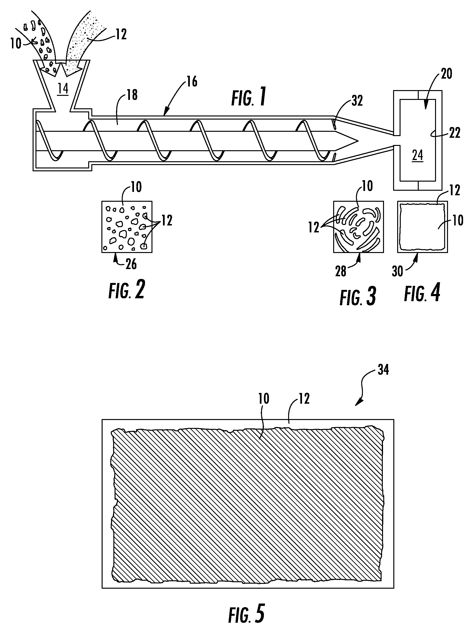
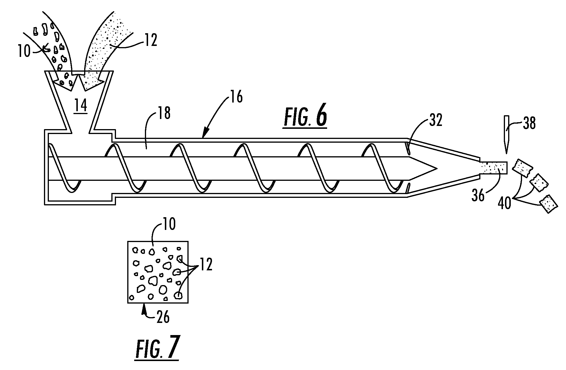
[0028] An ABS polymer resin is selected having a usable molten range of between about 440° F. and 470° F. wherein the ABS is typically compounded between the range of 440° F. and 455° F. and molded between about 455° F. and 470° F. The metallic alloy is formed using approximately 95% Tin and approximately 5% Antimony having a melting point of 463° F. In this example, the metallic alloy is mixed into the polymer resin using the compounding temperature range. Once the composition passes the check ring in the injection molding barrel, the temperature is elevated to the preferred molding temperature for the polymer of 470° F. causing the alloy to melt as the composition is injected into the mold cavity under pressure.

example 2

[0029] A PPS polymer resin is selected having a usable molten range of between about 560° F. and 610° F. wherein the PPS is typically compounded between the range of 560° F. and 565° F. and molded between about 565° F. and 610° F. The metallic alloy is formed using approximately 60% Tin and approximately 40% Zinc having a melting point of 585° F. In this example, the metallic alloy is mixed into the polymer resin using the compounding temperature range. Once the composition passes the check ring in the injection molding barrel, the temperature is elevated to the preferred molding temperature for the polymer of about 590° F. causing the alloy to melt as the composition is injected into the mold cavity under pressure.

[0030] Clearly, while certain polymers 10 and metal alloys 12 have been referred to by name, the present invention is applicable to any process utilizing the general teachings described herein as they would function equally well with a base polymer 10 and metal 12 select...


PUM

PropertyMeasurementUnit
Fractionaaaaaaaaaa
Fractionaaaaaaaaaa
Fractionaaaaaaaaaa

Abstract

A method is provided for forming a net shape molded component that includes an integral metallized coating or layer on the exterior surface thereof. The method includes injecting a carefully matched mixture of a molten polymer resin and a molten metallic alloy into a mold cavity under pressure. Due to the differential in material viscosities, the metal tends to migrate to the outer surface of the molded part when placed under pressure, ultimately creating a net shape molded part having a polymer core with a metallic layer at the exterior surfaces thereof. Further, the present invention provides for the compounding of a feedstock suitable for use in conjunction with the method described above.

Description

CROSS-REFERENCE TO RELATED APPLICATIONS [0001] This application is related to and claims priority from earlier filed U.S. Provisional Patent Application No. 60 / 670,991, filed Apr. 13, 2005, the contents of which are incorporated herein by reference.BACKGROUND OF THE INVENTION [0002] The present invention relates generally to polymer components having a metallic coating on an exterior surface thereof. More specifically, the present invention relates to molded polymer components with a metallic layer on their exterior surface wherein the metallic layer is entirely formed within the mold cavity before the part is removed from the mold. Further, the present invention is directed to a method of forming a molded polymer part to include a metallic layer about its exterior surface while the part remains in the mold. [0003] In the component manufacturing industry, it is highly desirable to form components using the fewest number of steps, thereby increasing the speed and efficiency while red...

Claims


Application Information

Patent Timeline
IPC IPC(8): B32B15/08B32B15/082C08G73/10
CPCB29C45/0013B29C2045/0015B29K2055/02B29L2009/003B29K2081/04B29K2705/00B29K2705/06B29K2069/00Y10T428/31678Y10T428/31692Y10T428/31696Y10T428/31699Y10T428/31935B29C45/00B29C45/16B32B15/082
Inventor MCCULLOUGH, KEVIN A.
Owner TICONA POLYMERS INC
Why Eureka
Try Eureka