
Corneal implant injector assembly and methods of use

a corneal implant and injector technology, applied in the field of corneal implant injectors, can solve the problems of inability to focus the image of the distant object on the retina, inability to locate the implant, and difficulty in locating the implant, so as to improve the storage of the implant.

Inactive Publication Date: 2006-10-19
REVISION OPTICS
View PDF39 Cites 125 Cited by
  • Summary
  • Abstract
  • Description
  • Claims
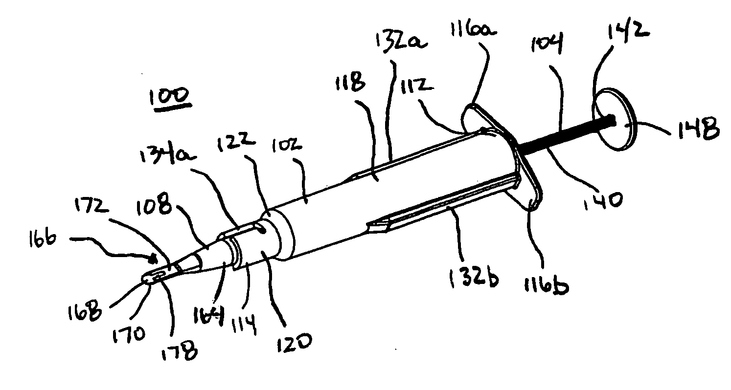
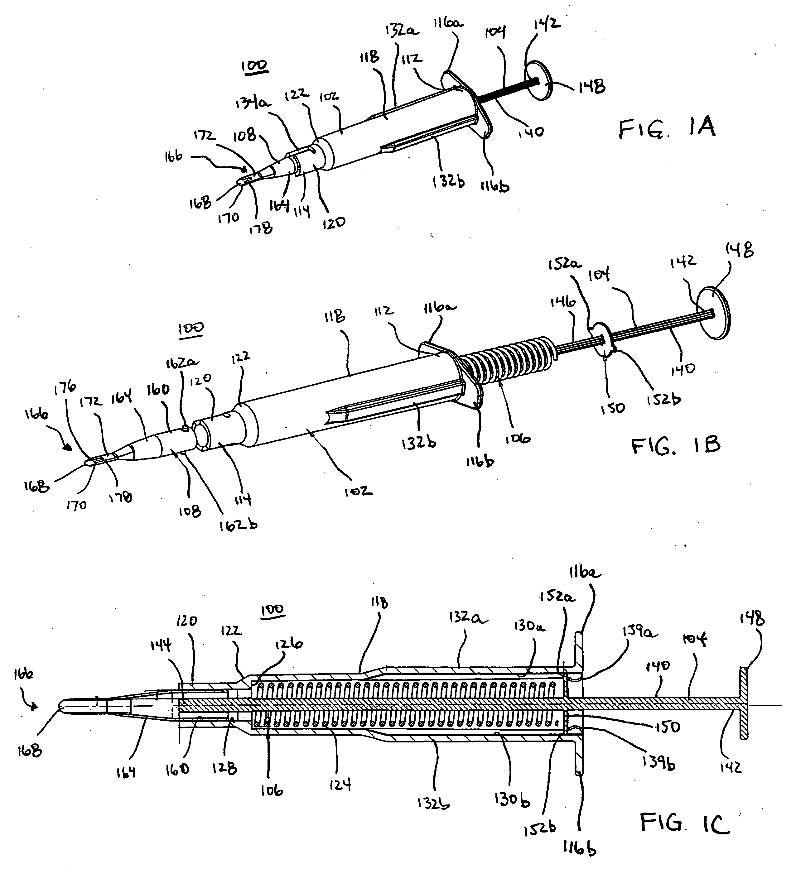
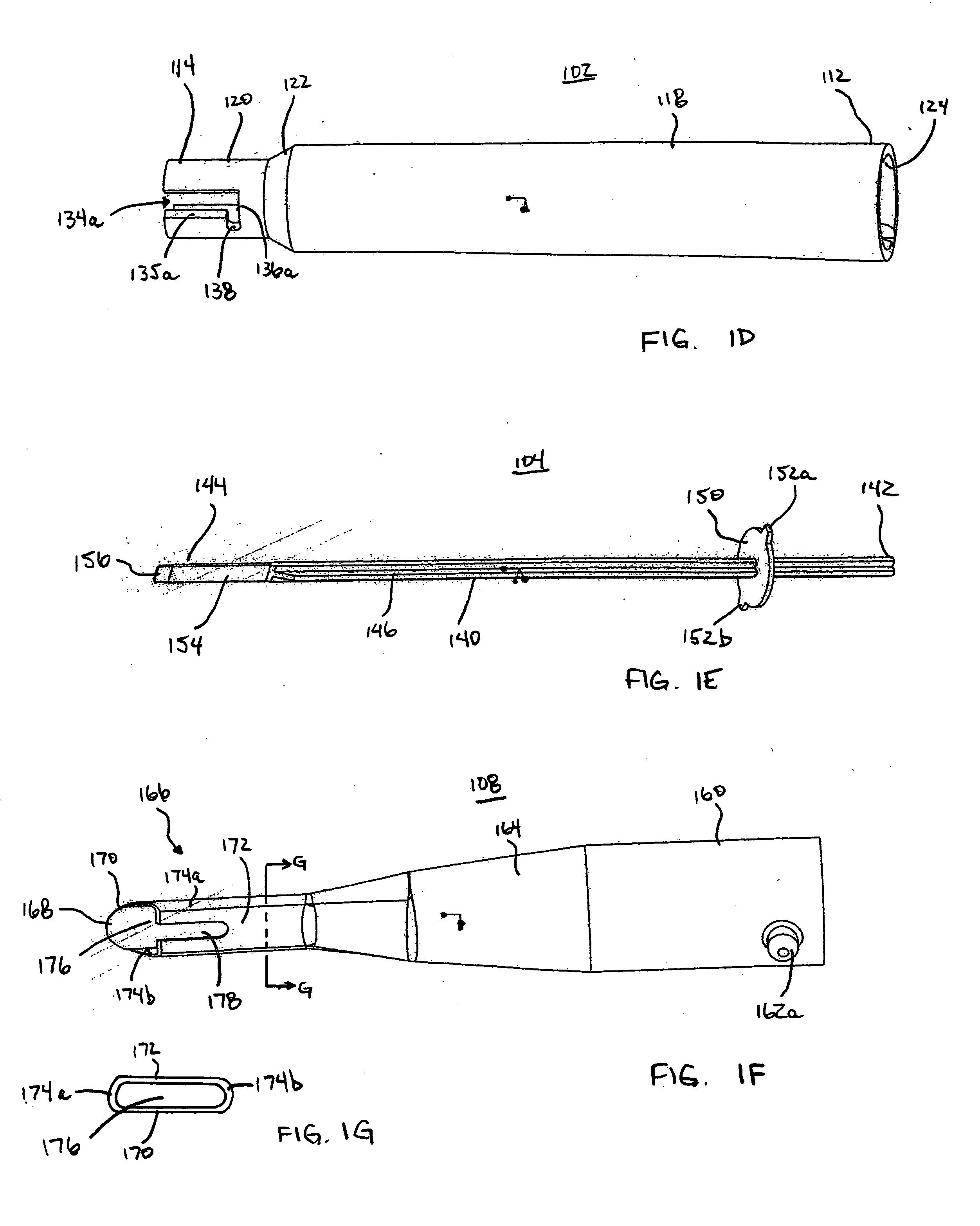
  • Application Information

AI Technical Summary

Benefits of technology

[0009] The present invention provides improved apparatus, systems, and methods for storing and retrieving a corneal implant and for depositing an implant onto the cornea during a refractive surgical procedure. The apparatus, systems, and methods provide for improved implant storage and retrieval capabilities over those of the prior art, and provide improved methods for deploying corneal implants during ophthalmologic surgical procedures.
[0010] Generally, an apparatus of the present invention is suitable for deploying a corneal implant. The apparatus includes a barrel portion, a plunger at least partially disposed within a portion of the barrel, and an injector tip formed integrally with or detachably attached to a distal portion of the barrel. The injector tip preferably includes a channel having a size and orientation adapted to store and then deploy a corneal implant. The plunger may be either a single structure or a combination structure, and preferably has an engagement tip adapted to safely engage and move the implant within the injector tip channel. The injector tip may advantageously be detachable from the remainder of the injector assembly so that the tip (with the implant already contained in the channel) may be stored separately in a container charged with a storage medium. Alternatively, the entire injector assembly may be stored in the storage medium in cases where the injector tip is or is not detachable from the remainder of the assembly.

Problems solved by technology

Deviations from the normal shape of the corneal surface, however, produce errors of refraction in the visual process so that the eye becomes unable to focus the image of the distant object on the retina.
In the case of a corneal implant, locating the implant is complicated by both the size and the transparency of the implant.
Due to this small size, physically grasping the implant from the storage fluid using tweezers, or some similar operation, is simply not practical.
Isolating the implant in this manner, however, subjects the implant to mechanical forces, which could lead to a loss of the implant.
Imparting such force upon the implant, however, can also damage the implant.
Using force imparting tools to hold the implant is therefore not desirable.
Prior isolation techniques were therefore difficult, time-consuming, and created additional steps, which could also lead to implant contamination.
Problematically, the step of unfolding the implant on the cornea surface could cause serious trauma to the cornea surface.
This trauma can lead to the formation of edema, or other deleterious responses that lead to rejection or displacement of the implant.

Method used


Image

  • Corneal implant injector assembly and methods of use
  • Corneal implant injector assembly and methods of use
  • Corneal implant injector assembly and methods of use

Examples


Embodiment Construction

[0035] Before the present invention is described, it is to be understood that this invention is not limited to particular embodiments described, as such may, of course, vary. It is also to be understood that the terminology used herein is for the purpose of describing particular embodiments only, and is not intended to be limiting, since the scope of the present invention will be limited only by the appended claims.

[0036] Unless defined otherwise, all technical and scientific terms used herein have the same meaning as commonly understood by one of ordinary skill in the art to which these inventions belong. Although any methods and materials similar or equivalent to those described herein can also be used in the practice or testing of the present invention, the preferred methods and materials are now described. All publications mentioned herein are incorporated herein by reference to disclose and describe the methods and / or materials in connection with which the publications are cit...


PUM


Abstract

A corneal implant injector assembly includes a barrel, a plunger, and an injector tip with a channel having a size and orientation adapted to store and deliver a corneal implant. The corneal implant is preferably stored in the channel in a contracted state. The plunger has an implant engagement tip for engaging and moving the implant within the channel and to deploy the implant. In some embodiments, the injector tip is selectively detachable from the remaining portion of the injector assembly.

Description

FIELD OF THE INVENTION [0001] The present invention relates to apparatus, systems, and methods for implanting corneal implants to the corneal surface of the eye. BACKGROUND OF THE INVENTION [0002] The eye works on a principle very similar to that of a camera. The iris—the colored portion of the eye about the pupil—functions like a shutter to regulate the amount of light admitted to the interior of the eye. The cornea and natural lens focus the rays of light on the retina. The retina then transmits the image of the object viewed to the brain via the optic nerve. Normally, these light rays are focused exactly on the retina, which permits the distant object to be seen distinctly and clearly. Deviations from the normal shape of the corneal surface, however, produce errors of refraction in the visual process so that the eye becomes unable to focus the image of the distant object on the retina. Hyperopia, or “farsightedness,” is an error of refraction in which the light rays from a distan...

Claims


Application Information

Patent Timeline
Patent Type & Authority Applications(United States)
IPC IPC(8): A61F9/00
CPCA61F2/143A61F2/148
Inventor LE, ALAN NGOCFORSBERG, JEFFCUNANAN, CRYSTAL M.VATZ, ALEXANDER
Owner REVISION OPTICS
Learn More