Data transmitter

Inactive Publication Date: 2006-10-19
PANASONIC CORP
View PDF5 Cites 5 Cited by
  • Summary
  • Abstract
  • Description
  • Claims
  • Application Information

AI Technical Summary

Benefits of technology

[0016] As described above, according to the present invention, data transmission is directly performed between an external device connected by a bus such as IEEE 1394 and a working memory connected to a bus to which the CPU is connected, whereby the performan

Problems solved by technology

This correlation-establishment also causes the performance of the data transmission to deteriorate.
The performance deterioration in the data transmission described above produces p

Method used


Image

  • Data transmitter
  • Data transmitter
  • Data transmitter

Examples


Example

[0022] Hereinafter, preferred embodiments of the present invention will be described with reference to the accompanying drawings.

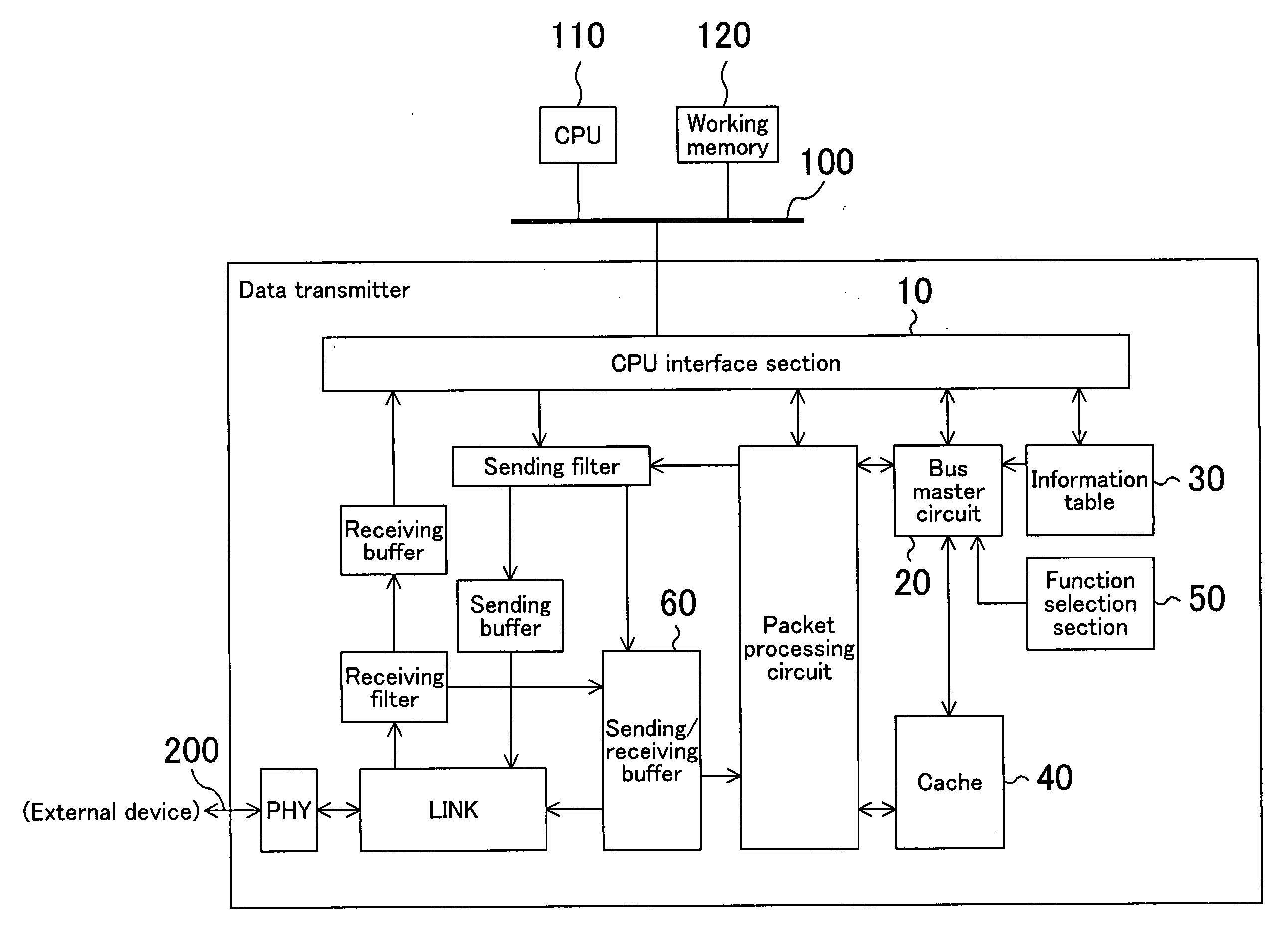
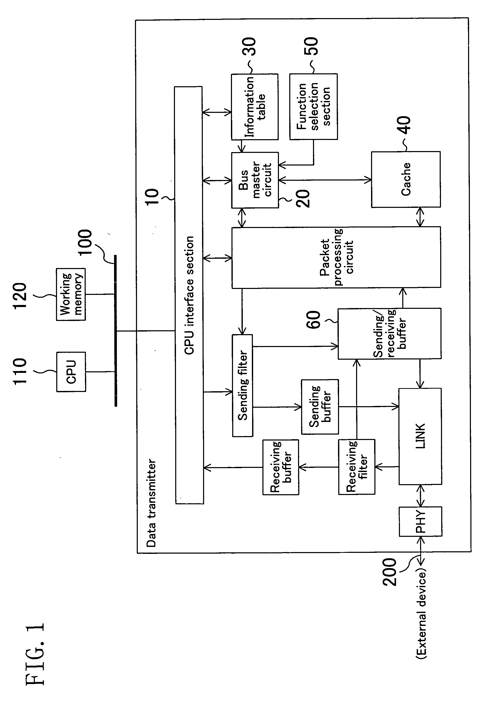
[0023]FIG. 1 illustrates a data transmitter according to an embodiment of the present invention. The data transmitter of this embodiment includes a bus master circuit 20, an information table 30, a cache 40, and a function selection section 50.

[0024] The bus master circuit 20 obtains the right to use a CPU bus 100 to directly perform data transmission to or from a working memory 120 through a CPU interface section 10 and the CPU bus 100. In this case, the bus master circuit 20 refers to the information table 30 and converts a virtual address related to a request made from an external device to a real address in the working memory 120. The bus master circuit 20 then performs transmission of data in an amount indicated by transmission information stored in the information table 30 to or from this real address. More specifically, the bus master circuit 20 c...


PUM


Abstract

A data transmitter includes a bus master circuit. The bus master circuit obtains the right to use a CPU bus and directly performs data transmission to and from a working memory connected to the CPU bus through a CPU interface section and the CPU bus.

Description

CROSS-REFERENCE TO RELATED APPLICATION [0001] This application claims priority under 35 USC § 119 to Japanese Patent Application No. 2005-117337 filed on Apr. 14, 2005, the entire contents of all of which are incorporated herein by reference. BACKGROUND OF THE INVENTION [0002] The present invention relates to a data transmitter, and particularly relates to a technique for data transmission between an external device connected to a data transmitter by an IEEE 1394 bus or the like and a working memory connected to a CPU bus. [0003] IEEE (Institute of Electrical and Electronic Engineers) 1394, which is a standard for performing device information (Config-ROM) exchange and command / data transfer using a virtual 48-bit address space on a single device (node), enables high-speed data transfer. In recent years, the IEEE 1394 has been adopted for the purpose of connecting a STB (set-top box) and a digital TV and thereby transferring EPG (electronic program guide) data. EPG data is large in s...

Claims


Application Information

Patent Timeline
IPC IPC(8): G06F13/00
CPCG06F12/1081G06F13/385G06F13/28
Inventor TABIRA, YOSHIHIRO
Owner PANASONIC CORP
Why Eureka
Try Eureka