Continuous food cooker

a continuous food and cooker technology, applied in the field of continuous food cookers, can solve the problems of inconvenient process, large amount of user intervention, and large equipment volume, and achieve the effects of convenient use, speed, and volum

Inactive Publication Date: 2006-10-26
NOTTINGHAM SPIRK DESIGN ASSOCS
View PDF29 Cites 9 Cited by
  • Summary
  • Abstract
  • Description
  • Claims
  • Application Information

AI Technical Summary

Benefits of technology

[0006] The present invention sets forth multiple novel improvements to the art of household food cooking devices. These improvements involve the consistency, volume, speed, and conveni

Problems solved by technology

Because this type of equipment is purposefully designed for large scale continuous production, the equipment is usually bulky, heavy, and expensive.
Existing food cookers for the common household require a significant amount of user intervention.
This process is inconvenient for the user because it is time consuming and must be repeate

Method used


Image

  • Continuous food cooker
  • Continuous food cooker
  • Continuous food cooker

Examples


first embodiment

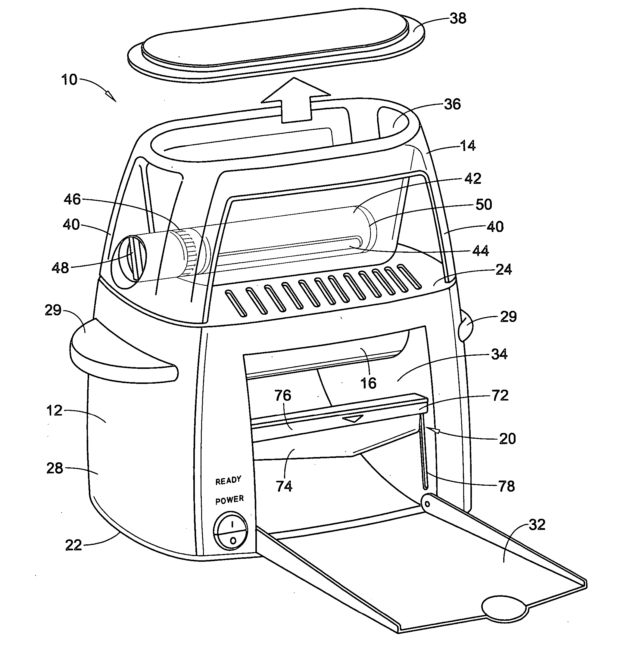
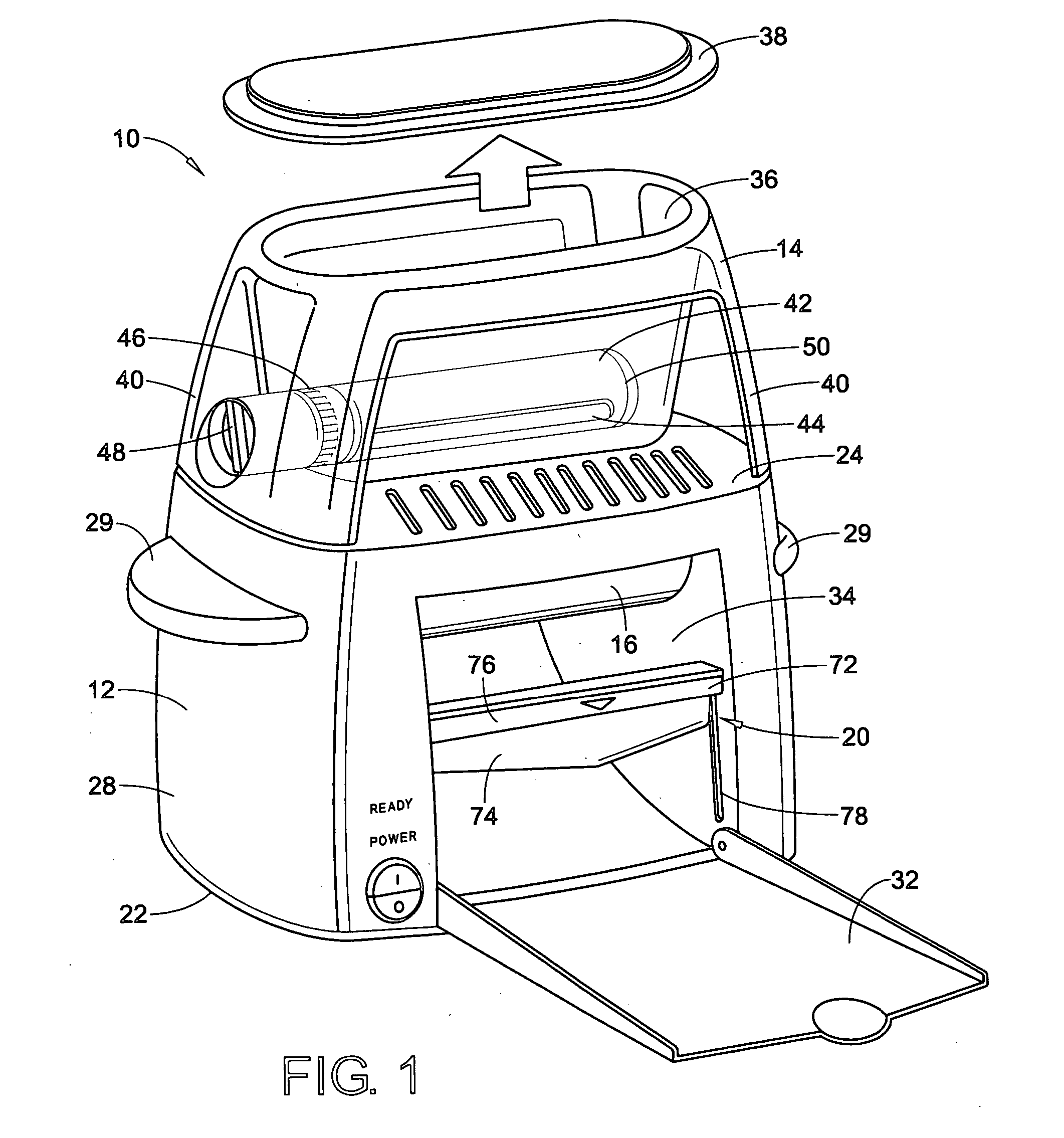
[0030] With reference to FIG. 1, a continuous food cooker 10 is shown which generally comprises a frame or housing 12, a food mixture hopper 14, a hot roller assembly 16, a hot roller drive assembly 18 and a cutter assembly 20. The housing generally includes a base 22, a top panel 24, a rear panel 26, a left and right side panel 28, 30, and a forward facing fold down dispensing tray 32. The dispensing tray has two positions, an upright closed position and an open position. When the dispensing tray 32 is in the upright closed position, a hot roller cavity area 34 is defined directly behind the dispensing tray 32. Generally, the hot roller assembly 16 is located in the upper portion of the hot roller cavity area 34. In addition, the cutter assembly 20 is located in the forward facing region of the hot roller cavity 34. The housing may be formed of a light weight plastic material, yet resilient enough to withstand high temperature. The base, the top panel, the rear panel and the side p...

fifth embodiment

[0041] Now with reference to FIG. 5, the rollers 552, 554 is shown. In this case, the rollers 552, 554 have no surface features along a cylindrical outer skin 557. In fact, as the food mixture enters the channel between the rollers 552, 554, the resulting cooked food product will have a very smooth surface on either side of the food product. By way of example, this embodiment of the rollers 552, 554 may be used in making pancakes or cooking bacon. In addition, one particular advantage of using the continuous food cooker to cook bacon using the rollers 552, 554 is that it results in healthier bacon with less fat, grease, and oil as compared to conventional methods of cooking bacon. Pressure exerted onto the bacon as it passes between the heated rollers 552, 554 not only facilitates the cooking of the bacon, but also serves to squeeze out excess oil, fat and other greases that are a result of the cooking process. In the case of cooking thin sliced meat products (such as bacon, chicken...

sixth embodiment

[0042] Now with reference to FIG. 6, the continuous food cooker utilizing a pair of rollers 652, 654 is shown. In this embodiment, the rollers 652, 654 are particularly suited for cooking doughy-type products such as cookies. The surface features of the rollers 652, 654 consist of circular or oval-like depressions 655 in a cylindrical outer skin 657 of the roller 652, 654. As before, any number of depressions 655 may be arranged along the outer skin 657. To further illustrate the depressions 655 in the rollers 652, 654, FIG. 6A illustrates the side elevation view of a driven end of the rollers 652, 654. The dashed lines shown in FIG. 6A would represent the overall width and depth of the depressions 655 in a cross-sectional view of the rollers 652, 654. In this embodiment, the rollers 652, 654 may be located in close proximity to one another such that the cylindrical outer skin 657 of each roller would be nearly touching the other. In addition, the two rollers 652, 654 would be synch...


PUM


Abstract

The present invention relates to a portable household food cooker capable of receiving a food mixture and producing food items in a continuous fashion. The continuous food cooker generally includes a housing and a hopper. The hopper is disposed above the housing for receiving the food mixture and for dispensing the food mixture into the cooker. The continuous food cooker also includes a hot roller assembly for forming and cooking the food mixture, a hot roller drive assembly operatively attached to at least one roller, and a cutter for cutting the produced food item at a desired length. The hot roller assembly includes at least one rotatable roller and at least one heating element for heating the at least one roller. The at least one roller and the at least one heating element are disposed internally to the housing.

Description

[0001] A claim for domestic priority is made herein under 35 U.S.C. §119(e) to U.S. Provisional App. Ser. No. 60 / 673,114 filed on Apr. 20, 2005 and U.S. Provisional App. Ser. No. 60 / 689,215 filed on Jun. 10, 2005, the entire disclosures of which is incorporated herein by reference.BACKGROUND [0002] The present invention relates to devices for producing food products in a continuous fashion. Particularly, the present invention is directed to the art of food production for the home and other small scale production settings. [0003] Generally, large scale food production equipment that mold, cook, and fill food products are known in the art. Because this type of equipment is purposefully designed for large scale continuous production, the equipment is usually bulky, heavy, and expensive. However, the need for continuous food production equipment not only exists for large scale production facilities but for the common household as well. [0004] Existing food cookers for the common househo...

Claims


Application Information

Patent Timeline
IPC IPC(8): A23P1/00
CPCA47J37/049A21C11/08
Inventor SAUNDERS, CRAIG M.KALMAN, JEFFREYVITANTONIO, MARC L.SIMEON, JAYSON C.
Owner NOTTINGHAM SPIRK DESIGN ASSOCS
Why Eureka
Try Eureka