Fuel Injection System And Method Of Operation For A Gaseous Fuelled Engine With Liquid Pilot Fuel Ignition

a technology of fuel injection system and liquid pilot fuel, which is applied in the direction of combustion air/fuel air treatment, machines/engines, mechanical equipment, etc., can solve the problems of fuel deposits that interfere with the operation or performance of the fuel injection valve, and achieve the effect of preventing the condensation of pilot fuel and lowering the final boiling poin

Inactive Publication Date: 2006-10-26
WESTPORT POWER
View PDF9 Cites 12 Cited by
  • Summary
  • Abstract
  • Description
  • Claims
  • Application Information

AI Technical Summary

Benefits of technology

[0069] In a preferred method the gaseous fuel is introduced into the combustion chamber by injecting the gaseous fuel directly into the combustion chamber through a gaseous fuel nozzle that is mounted in the cylinder head with the gaseous fuel nozzle protruding into the combustion chamber. The method further comprises thermally insulating the gaseous fuel nozzle so that surfaces that can come into contact with pilot fuel inside the combustion chamber can maintain a surface temperature that is not significantly lower than the final boiling point of the liquid pilot fuel. Preferably, the nozzle can absorb and retain heat from the combustion process to maintain a surface temperature that is higher than the final boiling point of the liquid pilot fuel so that pilot fuel does not condense thereon.
[0070] The engine's cylinder head is typically cooled by directing a liquid coolant through passages provided inside the cylinder head. The cooling effect of the cylinder head and the liquid pilot fuel flowing through the injection valve both act to cool the nozzle surface. As disclosed herein, to prevent condensation of the pilot fuel on the nozzle surface, the nozzle can be thermally insulated so that it can maintain a surface temperature that is higher than the final boiling point of the pilot fuel. Diesel fuel has been used as an example herein, but those skilled in the technology will understand that less insulation can be employed if a pilot fuel with a lower final boiling temperature is employed instead of diesel fuel because the surface temperature could be maintained at a lower temperature and still be above the final boiling point of the selected pilot fuel. For example, if the temperature of the cylinder head's firedeck is about 200° C. and the fuel injection nozzles are also maintained at about this temperature, a pilot fuel with a final boiling point less than 200° C. would not condense on the nozzle surfaces. By way of example, kerosene and some fuels formulated for jet engines have lower final boiling points compared to diesel fuels.

Problems solved by technology

A surface temperature would be “significantly” below the final boiling point of the pilot fuel if it results in condensation of pilot fuel compounds and the formation of deposits that interfere with the operation or performance of the fuel injection valve.

Method used


Image

  • Fuel Injection System And Method Of Operation For A Gaseous Fuelled Engine With Liquid Pilot Fuel Ignition
  • Fuel Injection System And Method Of Operation For A Gaseous Fuelled Engine With Liquid Pilot Fuel Ignition
  • Fuel Injection System And Method Of Operation For A Gaseous Fuelled Engine With Liquid Pilot Fuel Ignition

Examples


Embodiment Construction

)

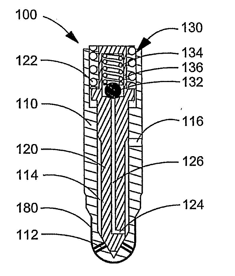
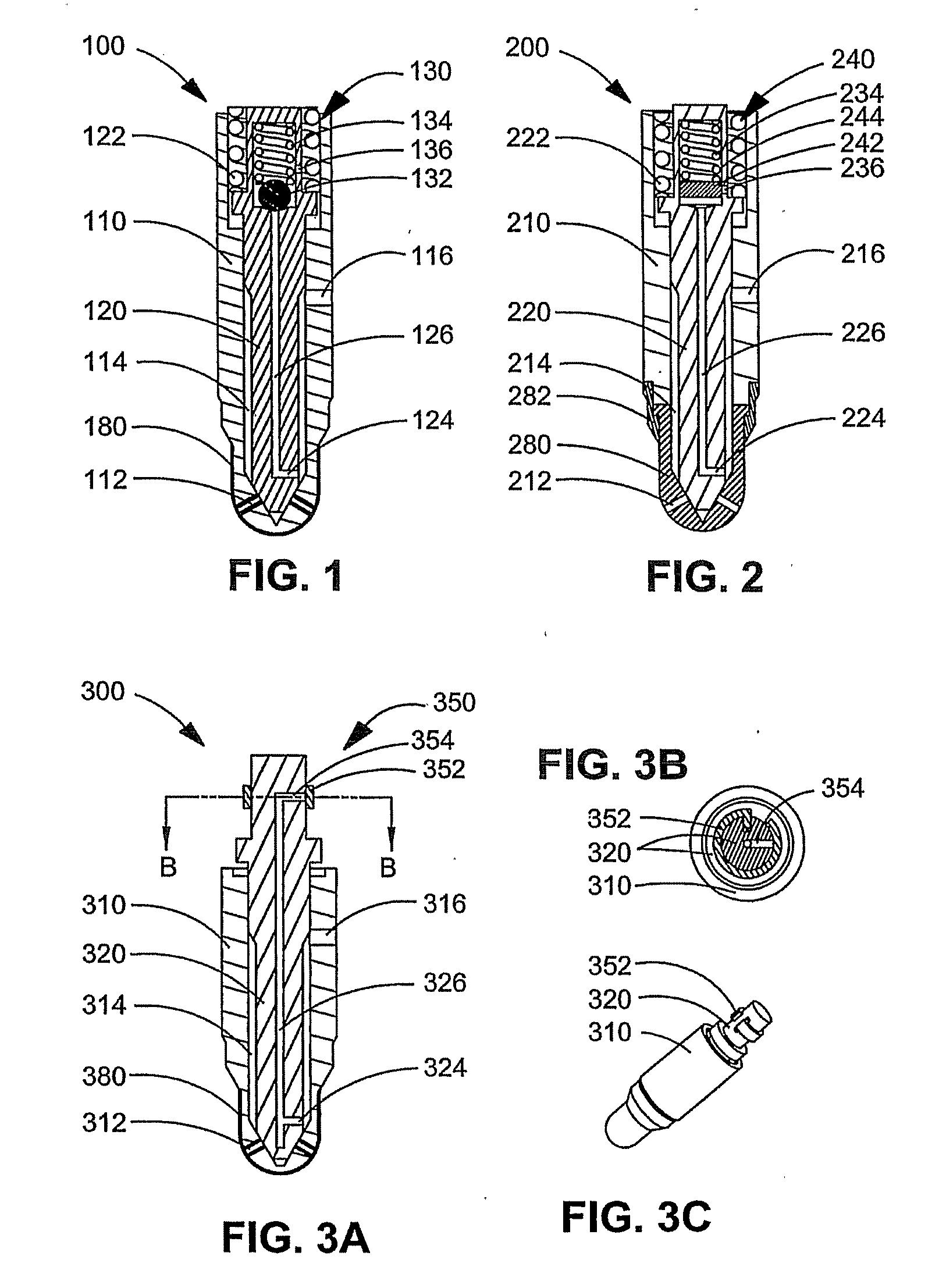
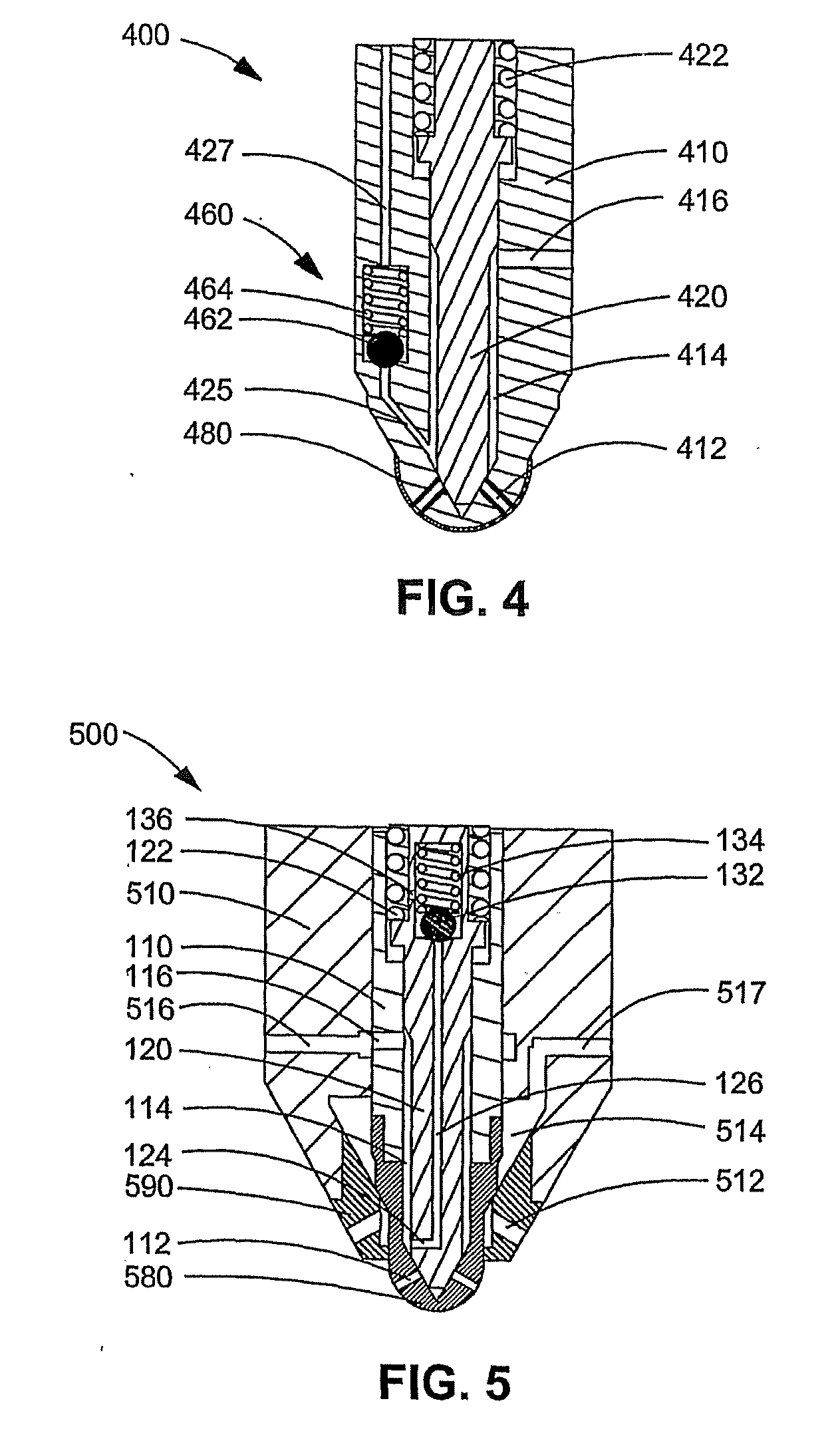
[0081] A number of preferred embodiments are provided of fuel injection valves that can be employed in a fuel injection system for a gaseous-fuelled internal combustion engine that employs a liquid pilot fuel. The figures illustrate the nozzle end of a pilot fuel injection valve with cooling features to keep the liquid pilot fuel within the valve body cooler than the lowest initial boiling temperature of the pilot fuel that occurs within the pilot fuel injection valve. Also provided are thermal insulation features for reducing the cooling influence of the cylinder head and the liquid pilot fuel on the nozzle's outer surface. To prevent a significant amount of pilot fuel from condensing on the nozzle's outer surface, the nozzle's outer surface is thermally insulated to prevent the surface temperature from dropping significantly below the final boiling point of the liquid pilot fuel when the engine is running. In preferred embodiments the heat of combustion generated by the running e...


PUM


Abstract

A pilot fuel injection valve is mountable in a cylinder head of an engine and injects a liquid pilot fuel directly into a combustion chamber. The pilot fuel injection valve comprises a cooling system to keep the pilot fuel at a temperature that is lower than the lowest initial boiling point for the pilot fuel that occurs inside the fuel injection valve. The pilot fuel injection valve further comprises a thermally insulated nozzle having an outer surface that is not cooled by the cooler cylinder head and the cooler pilot fuel held inside the fuel injection valve. During operation, the nozzle's outer surface can be heated to a temperature that is not significantly lower than the final boiling point of the pilot fuel so that a significant amount of pilot fuel does not condense on the nozzle surface during engine operation.

Description

CROSS-REFERENCE TO RELATED APPLICATION(S) [0001] This application is a continuation of International Application No. PCT / CA2004 / 001668, having an international filing date of Sep. 10, 2004, entitled “A Fuel Injection System And Method Of Operation For A Gaseous Fuelled Engine With Liquid Pilot Fuel Ignition”. International Application No. PCT / CA2004 / 001668 claimed priority benefits, in turn, from Canadian Patent Application No. 2,442,601 filed Sep. 26, 2003. International Application No. PCT / CA2004 / 001668 is hereby incorporated by reference herein in its entirety.FIELD OF THE INVENTION [0002] The present invention relates to a fuel injection system and method of operation for a gaseous-fuelled engine with liquid pilot fuel ignition. BACKGROUND OF THE INVENTION [0003] Developments in combustion engine technology have shown that compression ignition engines, frequently referred to as diesel-cycle engines, can be fuelled with gaseous fuels instead of diesel without sacrifices in perfor...

Claims


Application Information

Patent Timeline
Patent Type & Authority Applications(United States)
IPC IPC(8): F02B7/06F02B7/08F02M43/04F02D19/10F02M45/08F02M53/04F02M61/18
CPCF02D19/0605F02D19/10F02M31/20F02M43/04F02M45/086F02M53/043F02M53/08F02M61/166F02M61/18F02M61/1806F02M2200/9007F02D19/0694F02M21/0263F02M63/0036F02M63/0054F02M55/002F02M2200/46Y02T10/30
Inventor RANDALL, MARK
Owner WESTPORT POWER
Why Eureka
Try Eureka