Composite structure having a non-planar interface and method of making same

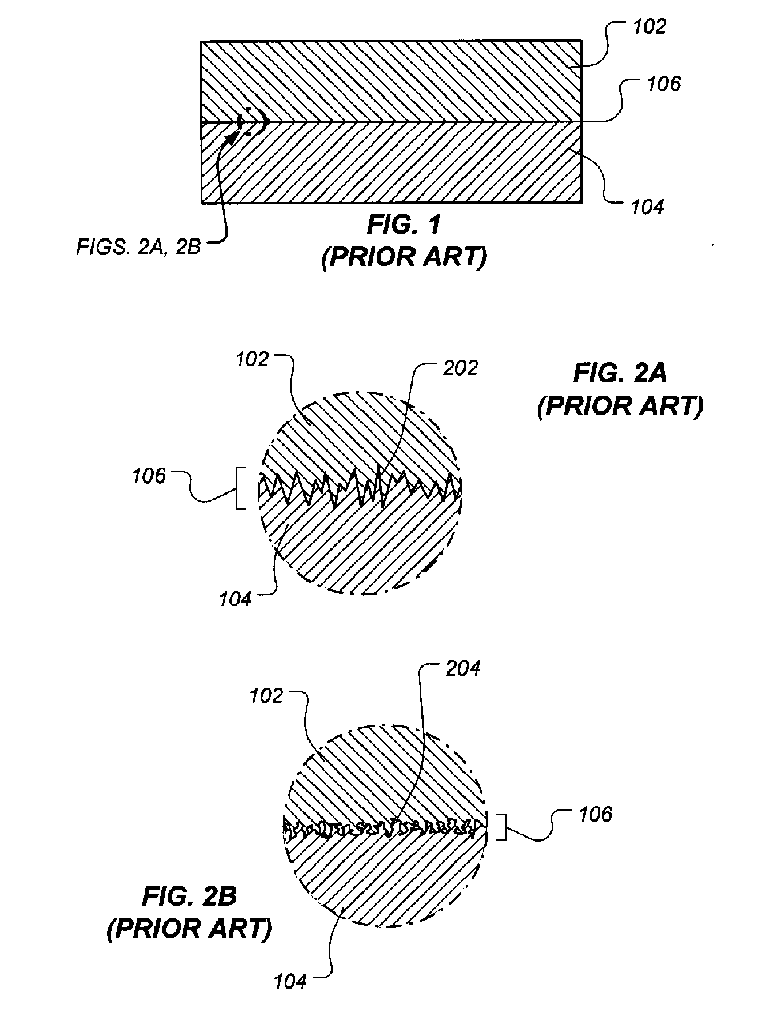
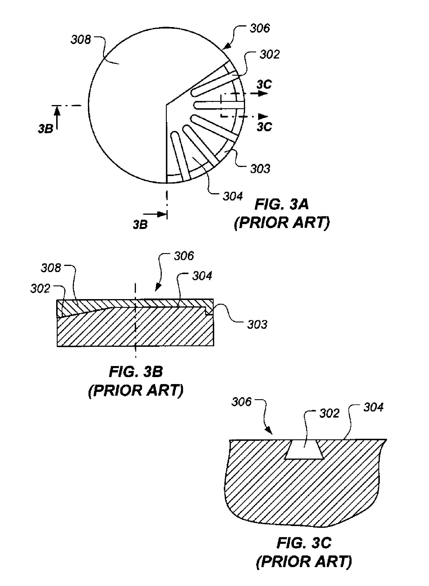
a non-planar interface, composite structure technology, applied in the direction of drill bits, drilling accessories, earthwork drilling and mining, etc., can solve the problems of limiting the useful strength of these structures, high torsion load, and abrasive materials on the cutting surface of the structur

Inactive Publication Date: 2006-10-26
REEDHYCALOG LP
View PDF42 Cites 108 Cited by
  • Summary
  • Abstract
  • Description
  • Claims
  • Application Information

AI Technical Summary

Problems solved by technology

For example, the body of a drilling bit, such as those used in oilfield operations, is subjected to high torsion loads during drilling, while the cutting surfaces thereof encounter very hard, abrasive materials.
The effects of this discontinuity on mechanical response of the union typically limit the useful strength of these structures.
The additional processing may, in some instances, also be costly.
For example, the electron beam, laser, or other localized, intense heat source equipment used to melt areas of the interface surface 204 may be very expensive to purchase, maintain, and operate.
While such techniques often are successful in retaining disparate materials together, the additional machining steps required to form the grooves 302, 303 may add substantial cost and complexity to the finished product.
While such structures address the property compatibility issues described above, their complexity often adds prohibitive fabrication cost and may be incompatible with preferred fabrication methods.

Method used


Image

  • Composite structure having a non-planar interface and method of making same
  • Composite structure having a non-planar interface and method of making same
  • Composite structure having a non-planar interface and method of making same

Examples


Embodiment Construction

[0045] Illustrative embodiments of the invention are described below. In the interest of clarity, not all features of an actual implementation are described in this specification. It will of course be appreciated that in the development of any such actual embodiment, numerous implementation-specific decisions must be made to achieve the developer's specific goals, such as compliance with system-related and business-related constraints, which will vary from one implementation to another. Moreover, it will be appreciated that such a development effort might be complex and time-consuming but would nevertheless be a routine undertaking for those of ordinary skill in the art having the benefit of this disclosure.

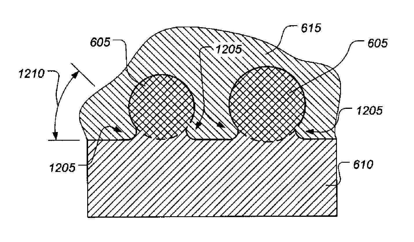
[0046] The present invention relates to a structure comprising disparate materials joined along a non-planar interface that exhibits, in one illustrative embodiment, an interlocking geometry and a method for fabricating the structure. While it is not so limited, the structure of...


PUM

PropertyMeasurementUnit
draft angleaaaaaaaaaa
draft anglesaaaaaaaaaa
draft angleaaaaaaaaaa

Abstract

A composite structure includes a first portion comprising a first metallic material, a monolayer of particles extending into and bonded with the first portion, and a second portion comprising a second material, the second portion bonded with the monolayer of particles and extending into interstices between the particles. A method for fabricating a composite structure includes bonding a monolayer of particles to a first portion comprising a first metallic material, such that the monolayer of particles extends into the first portion and bonding a second portion comprising a second material to the monolayer of particles, such that the second portion extends into interstices between the particles.

Description

BACKGROUND OF THE INVENTION [0001] 1. Field of the Invention [0002] This invention relates to a composite structure including a non-planar interface and a method of making the composite structure. [0003] 2. Description of the Related Art [0004] Metallic structures often comprise two or more joined materials that have different properties and characteristics. Often such disparate materials are joined together into one component because portions of the component are subjected to different environments. For example, the body of a drilling bit, such as those used in oilfield operations, is subjected to high torsion loads during drilling, while the cutting surfaces thereof encounter very hard, abrasive materials. Accordingly, rock drilling bit bodies are generally made of steel, while the cutting surfaces often comprise tungsten carbide or polycrystalline diamond composites. Steel provides the material properties required to endure high torsion loads, while tungsten carbide or polycrysta...

Claims


Application Information

Patent Timeline
Patent Type & Authority Applications(United States)
IPC IPC(8): E21B10/36
CPCB22F7/02B22F7/04B22F2998/10C22C1/1036E21B10/5735B22F3/02B22F3/26
Inventor SRESHTA, HAROLDDRAKE, ERIC F.
Owner REEDHYCALOG LP
Why Eureka
Try Eureka