
Combined fuel cell aircraft auxiliary power unit and environmental control system

a fuel cell and auxiliary power technology, applied in the field of aircraft systems, can solve the problems of poor fuel efficiency, appreciable pollution of the airport environment, jet fuel uncombusted, and emissions of oxides of nitrogen (nox) emissions, and achieve the effect of reducing the weight and associated cost of aircraft operations

Active Publication Date: 2006-10-26
THE BOEING CO
View PDF39 Cites 81 Cited by
  • Summary
  • Abstract
  • Description
  • Claims
  • Application Information

AI Technical Summary

Benefits of technology

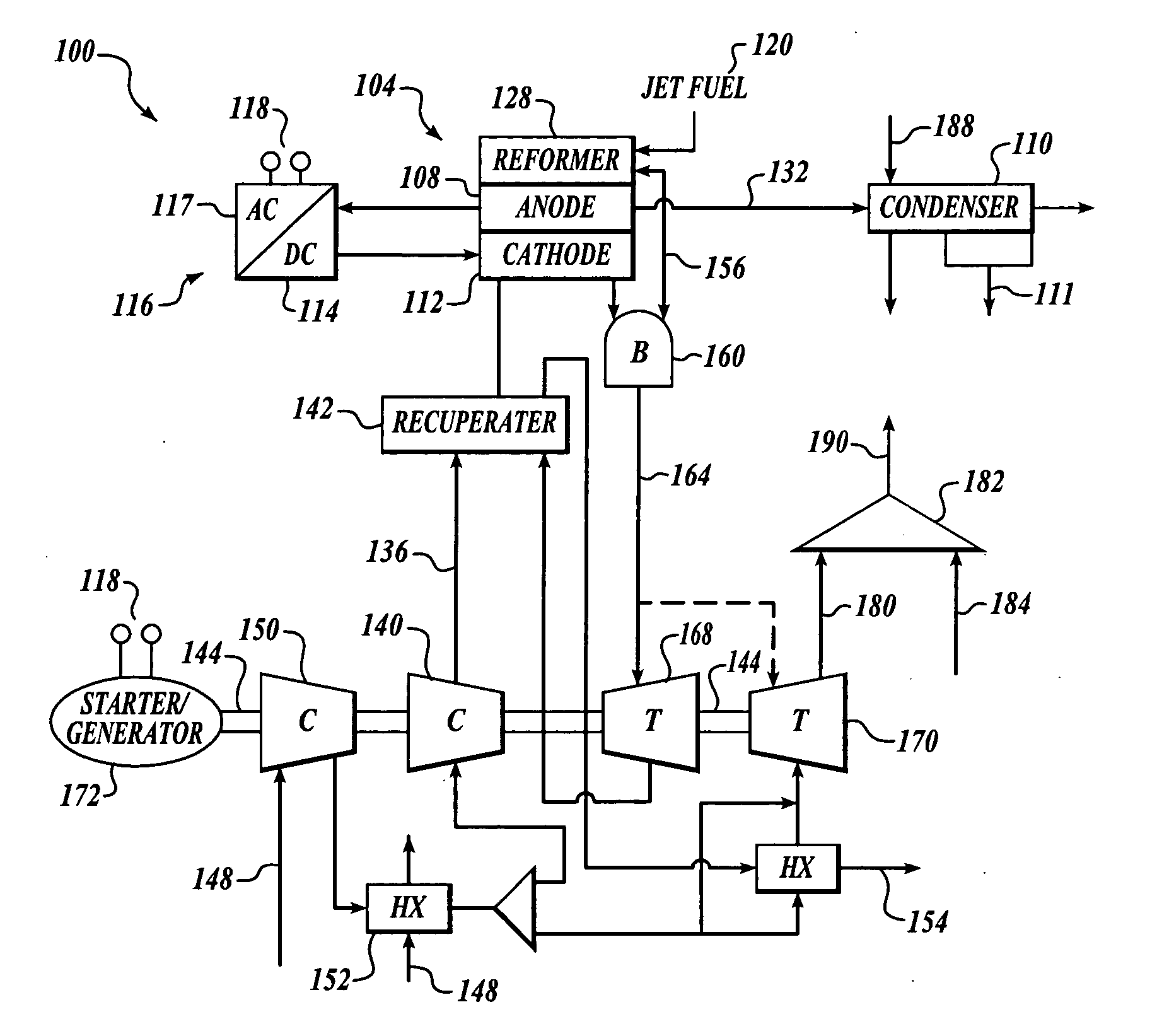
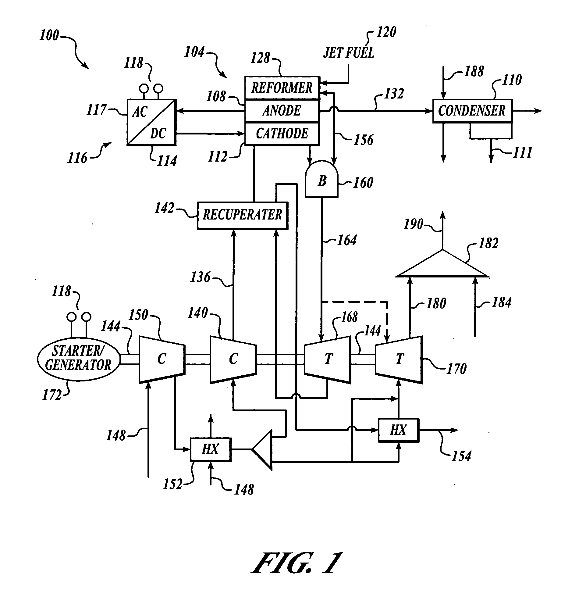
[0006] The present invention is directed to a combined fuel cell aircraft auxiliary power unit and environmental control system. Embodiments of the present invention may provide an efficient method for providing both electrical and pneumatic power, and may reduce the weight and associated cost of aircraft operations.

Problems solved by technology

Disadvantages of turbine APUs, however, may include poor fuel efficiency and appreciable pollution to an airport environment.
In the case of turbine APUs, the burning of fuel to drive the turbines leaves some jet fuel uncombusted and produces oxides of nitrogen (NOx) emissions.
Fuel cell APUs offer lower emissions than turbine-driven APUs, and are more fuel efficient, but are heavy and tend to loose efficiency at high altitudes.
Hybrid fuel cell APUs generally improve upon the efficiency of conventional turbine and fuel cell APUs and are lighter weight than pure fuel cell APUs, but provide only electrical power suitable for certain aircraft and not for others, including those that require compressed air to drive an environmental control system.
Alternately, the ECS can incorporate motors that are electrically powered by the aircraft engine generator or APU generator However, an ECS will penalize engine performance because its energy source is derived directly from the main engine or APU, capturing a significant amount of power.
Thus, conventional ECS packs that are pneumatically driven by the airplane engine or APU tend to be light weight, but are relatively inefficient.

Method used


Image

  • Combined fuel cell aircraft auxiliary power unit and environmental control system
  • Combined fuel cell aircraft auxiliary power unit and environmental control system
  • Combined fuel cell aircraft auxiliary power unit and environmental control system

Examples


Embodiment Construction

[0014] Combined fuel cell aircraft auxiliary power unit and environmental control systems and methods are disclosed. Many specific details of certain embodiments of the invention are set forth in the following description and in FIGS. 1 through 5 to provide a thorough understanding of such embodiments. One skilled in the art, however, will understand that the present invention may have additional embodiments, or that the present invention may be practiced without several of the details described in the following description.

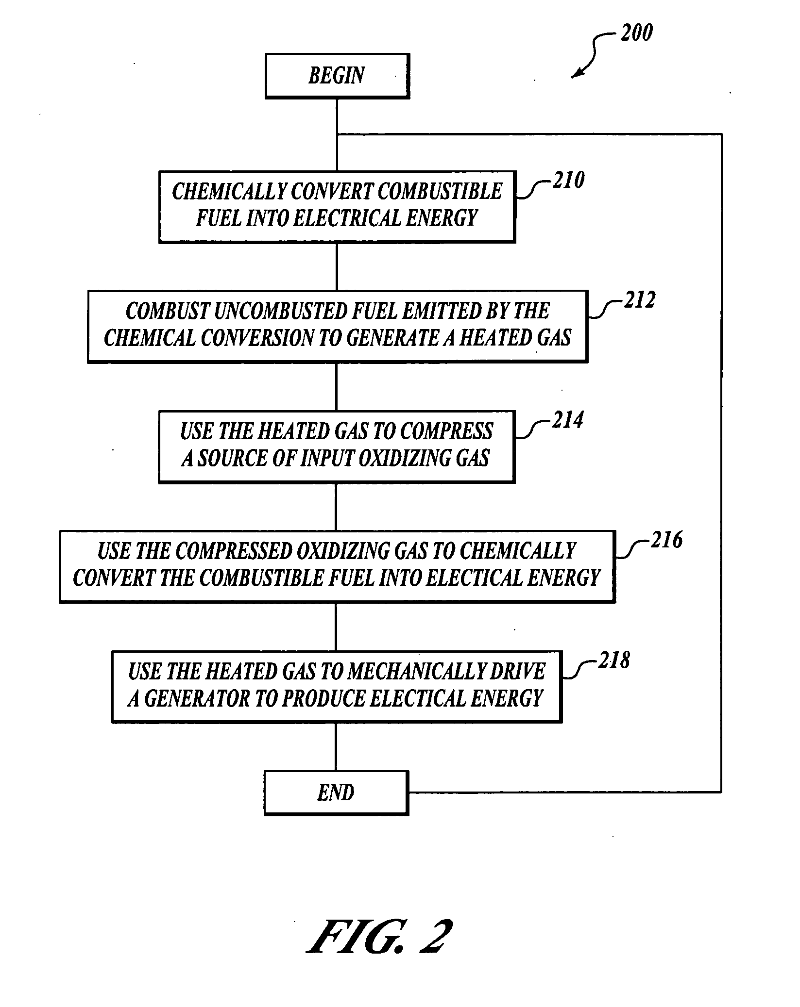
[0015] In general, embodiments of the present invention may provide a desired quality of electrical and pneumatic power. In one embodiment, combustible fuel is chemically converted into electrical energy by providing a supply of compressed air. Combustible fuel and air not consumed by the chemical process is collected and burned to drive a first high temperature power recovery turbine which, in turn, drives a first compressor to supply the compressed air. Compre...


PUM


Abstract

Combined aircraft hybrid fuel cell auxiliary power unit and environmental control system and methods are disclosed. In one embodiment, an auxiliary power unit includes a fuel cell component which chemically converts combustible fuel into electrical energy. Unutizlied fuel emitted by the fuel cell component is combusted by a burner to generate heated gas. The heated gas is received by and drives a turbine, which in turn drives a drive shaft. A compressor, coupled to the drive shaft, compresses a source of oxidizing gas for supplying compressed oxidizing gas to the fuel cell component and to an environmental control system. A heat exchanger controls the temperature of the pressurized air leaving the environmental control system to provide the cabin air supply. Finally, a generator is coupled to the drive shaft to be driven by the turbines to generate additional electrical energy.

Description

FIELD OF THE INVENTION [0001] The present disclosure relates generally to power supplies, and more specifically to aircraft systems that generate both electrical and pneumatic power. BACKGROUND OF THE INVENTION [0002] Auxiliary power units (APUs) are used in the aircraft industry to provide auxiliary power to onboard systems. APU systems may include turbine, fuel cell, and hybrid systems. Turbine-driven APUs burn jet fuel to drive a turbine, which in turn drives a generator to produce electrical energy. Fuel cells chemically convert fuel into electrical energy. Hybrid APUs utilize both turbine and fuel cell methods in its production of power. Each type of APU may be used to power onboard systems while the aircraft is on the ground, as well as when the aircraft is in flight. [0003] Disadvantages of turbine APUs, however, may include poor fuel efficiency and appreciable pollution to an airport environment. In the case of turbine APUs, the burning of fuel to drive the turbines leaves s...

Claims


Application Information

Patent Timeline
IPC IPC(8): B64D41/00
CPCB64D13/06Y02E60/50B64D2013/0611B64D2041/005H01M8/04014H01M8/04111H01M2008/1293H01M2250/20H01M2250/407Y02E60/563Y02T50/44Y02T50/53Y02T50/56Y02T90/32Y02T90/36Y02E60/525Y10S429/901B64D41/00Y02T50/40Y02T50/50Y02T90/40
Inventor FUCKE, LARSDAGGETT, DAVID L.
Owner THE BOEING CO
Learn More