Photo-luminescence liquid crystal display

a liquid crystal display and photoluminescence technology, applied in the direction of luminescnet screens, discharge tubes/lamp details, instruments, etc., can solve the problems of reducing the amount of uv light used for excitation of phosphors, reducing the life span, and significant optical loss, so as to achieve long life, prevent degradation, and high light efficiency

Inactive Publication Date: 2006-10-26
SAMSUNG ELECTRONICS CO LTD
View PDF4 Cites 80 Cited by
  • Summary
  • Abstract
  • Description
  • Claims
  • Application Information

AI Technical Summary

Benefits of technology

[0011] The present disclosure provides a photo-luminescence (PL) LCD with high light efficiency and long life span by preventing degradation of liquid crystals due to excitation of phosphor by ultraviolet (UV) light.

Problems solved by technology

The R, G, and B color filters each transmit only light of a specific wavelength that is one third of that of the white light, resulting in significant optical loss.
However, because some of the UV light is absorbed by liquid crystals, the amount of UV light used for excitation of phosphors decreases.
The absorbed UV light also degrades the liquid crystals, thus reducing their life span.
Furthermore, the LCD using some color filters instead of a color filter-free structure still suffers from optical loss.
Thus, the most challenging task for a PL LCD is to prevent degradation of liquid crystals due to UV light and obtain maximum light emission efficiency by absorbing a sufficient amount of light.

Method used


Image

  • Photo-luminescence liquid crystal display
  • Photo-luminescence liquid crystal display
  • Photo-luminescence liquid crystal display

Examples


Embodiment Construction

[0023] The present disclosure will now be described more fully with reference to the accompanying drawings, in which exemplary embodiments of the disclosure are shown.

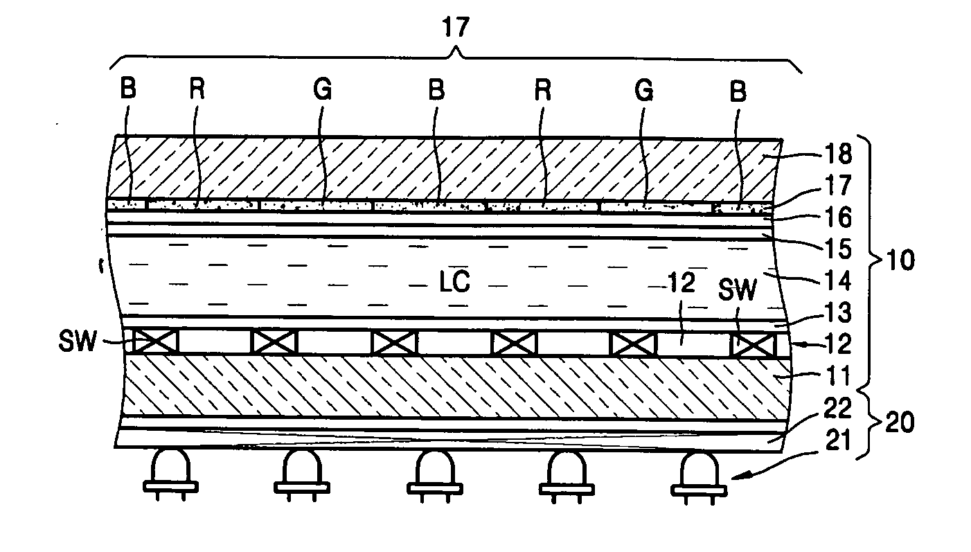
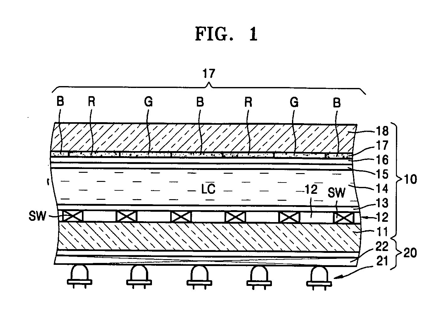
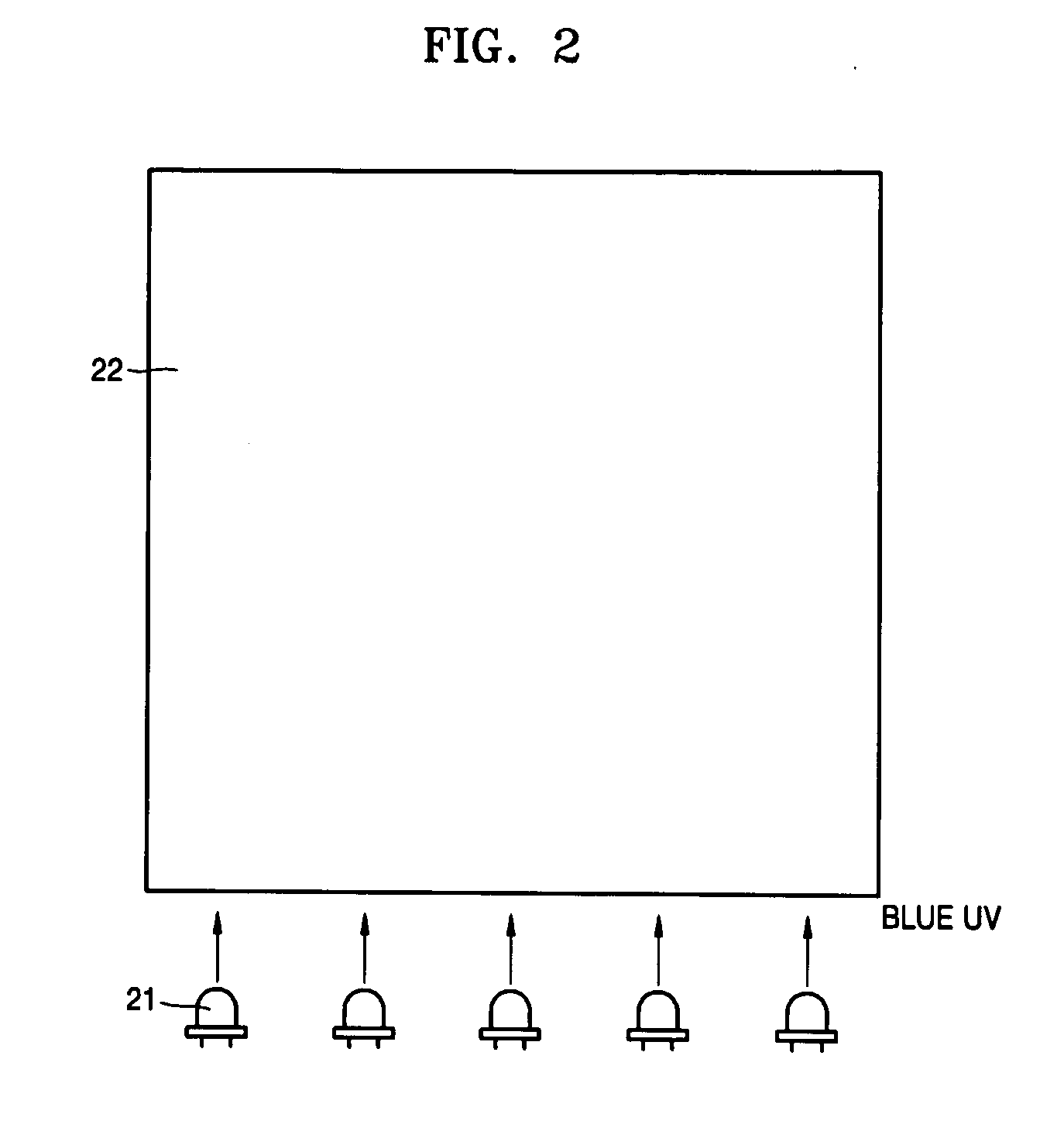
[0024] Referring to FIG. 1, an LCD according to an embodiment of the present disclosure includes a display panel 10 and a blue ultraviolet (UV) light source unit 20. The display panel 10 includes a front substrate 18 and a rear substrate 11 spaced from each other by a predetermined distance and a liquid crystal (LC) layer 14 sandwiched between the front and rear substrates 18 and 11.

[0025] A photo-luminescence (PL) layer 17 containing red (R), green (G), and blue (B) layers is disposed on an inner surface of the front substrate 18. A common electrode 16 and an upper alignment layer 15 are sequentially formed on the PL layer 17. A plurality of thin-film transistor (TFT) switching elements SW and a plurality of pixel electrodes 12 and a lower alignment layer 13 are sequentially disposed on the rear substrate 11. The PL...


PUM

PropertyMeasurementUnit
wavelengthaaaaaaaaaa

Abstract

Provided is a photo-luminescence (PL) LCD including: electrodes that are disposed on bottom and top surfaces of front and rear substrate and create an electric field in liquid crystals (LCs); a nano-dot (ND) PL layer that is disposed on the bottom surface of the front substrate and emits light when irradiated with ultraviolet (UV) light, and a UV backlight unit that is located behind the rear substrate and supplying UV light to the ND PL layer. The UV backlight unit is excited by blue UV light having a wavelength range of 360 to 460 nm to emit light. The PD LCD having the above-mentioned structure suppresses absorption of UV light by LC and degradation of the LC while providing high light efficiency.

Description

CROSS-REFERENCE TO RELATED PATENT APPLICATION [0001] Priority is claimed to Korean Patent Application No. 10-2005-0034014, filed on Apr. 25, 2005, in the Korean Intellectual Property Office, the disclosure of which is incorporated herein in its entirety by reference. BACKGROUND OF THE DISCLOSURE [0002] 1. Field of the Disclosure [0003] The present disclosure relates to a liquid crystal display (LCD) and a photo-luminescence (PL)-LCD with high light efficiency. [0004] 2. Description of the Related Art [0005] LCDs are non-emissive displays and need a separate backlight device to display an image on a screen. LCDs also require Red (R), Green (G), and Blue (B) color filters for their respective pixels to display a color image. [0006] The R, G, and B color filters respectively separate white light emitted by a backlight device into red, green, and blue. The R, G, and B color filters each transmit only light of a specific wavelength that is one third of that of the white light, resulting ...

Claims


Application Information

Patent Timeline
Patent Type & Authority Applications(United States)
IPC IPC(8): H01J1/62B82Y20/00C09K11/08C09K11/54C09K11/56C09K11/59C09K11/62C09K11/65C09K11/66C09K11/70C09K11/74C09K11/75C09K11/88C09K11/89G02F1/1335G02F1/13357
CPCB82Y20/00G02F2202/36G02F1/133617
Inventor CHOI, JAE-YOUNGKIM, BYUNG-KIIM, SEOUNG-JAELEE, EUN-SUNGCHO, KYUNG-SANGJANG, EUN-JOO
Owner SAMSUNG ELECTRONICS CO LTD
Why Eureka
Try Eureka