Method and Apparatus for Compressive Imaging Device

Inactive Publication Date: 2006-10-26
RICE UNIV
View PDF13 Cites 231 Cited by
  • Summary
  • Abstract
  • Description
  • Claims
  • Application Information

AI Technical Summary

Benefits of technology

[0014] A small number of detectors, even a single detector, can be used. Thus, the camera can be adapted to image at wavelengths of electromagnetic radiation that are currently impossible with conventional CCD and CMOS imagers. This feature is particularly advantageous, because in some cases the usage of many detectors is impossible or impractical, whereas the usage of a small number of detectors, or even a single de

Problems solved by technology

First, acquiring large amounts of raw image or video data (large N) can be expensive, particularly at wavelengths where CMOS or CCD sensing technology is limited.
Second, compressing raw data can be computationally demanding, particularly in the case of video.
In the former case, scheduled power-off periods could result in missing an important event entirely.
In the latter case, we require additional h

Method used


Image

  • Method and Apparatus for Compressive Imaging Device
  • Method and Apparatus for Compressive Imaging Device
  • Method and Apparatus for Compressive Imaging Device

Examples


Example

Example 1

Still Image Acquisition

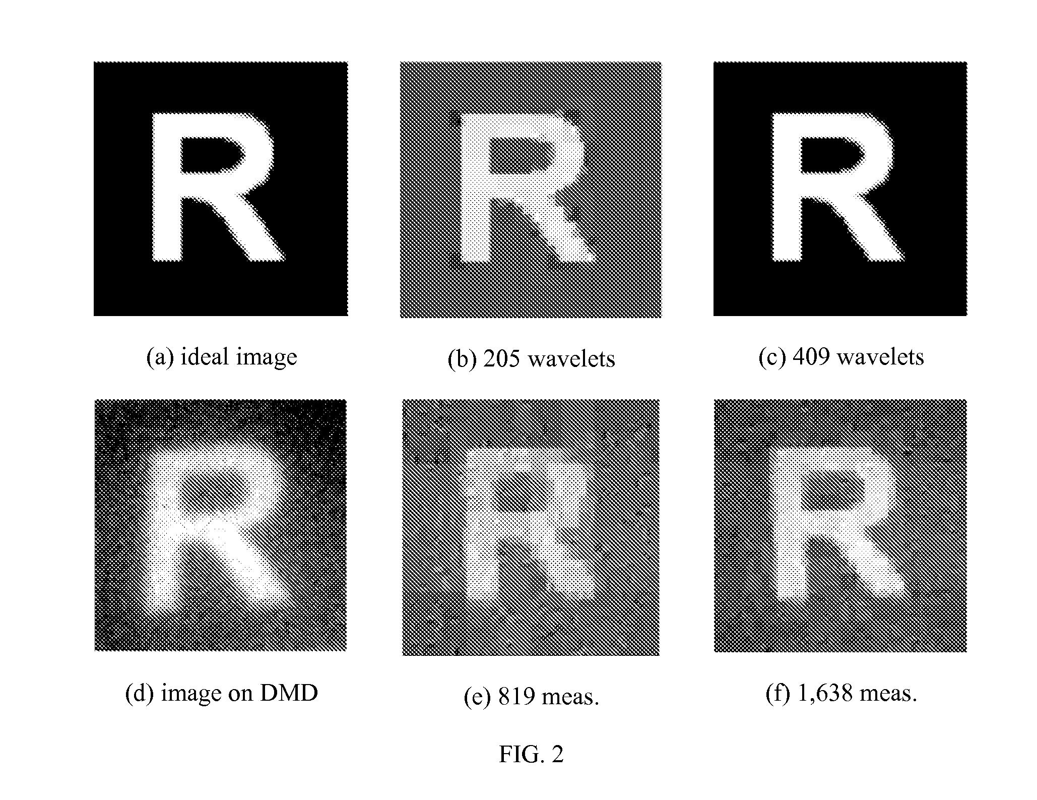
[0070] For an imaging experiment, we displayed a printout of the letter “R” in front of the camera; FIG. 2(a) shows the printout. For acquisition and reconstruction, we use an imaging resolution of N=64×64=4096. Since our test image is piecewise constant (with sharp edges) it can be sparsely represented in the wavelet domain. FIGS. 2(b) and 2(c) show the best K-term Haar wavelet approximation of the idealized image in FIG. 2(a) with K=205 and 409, respectively. Using M=819 and 1,638 measurements (roughly 4× the K used in (b) and (c)), we reconstructed the images shown in FIGS. 2(e) and 2(f) using the Dantzig Selector (see Candès, E., Tao, T., “The Dantzig selector: Statistical estimation when p is much larger than n,” (2005) Preprint), a robust scheme for CS reconstruction. In all cases Haar wavelets were used for approximation or reconstruction. This preliminary embodiment confirms the feasibility of the CI approach; resolution of minor calibration...

Example

Example 2

Video Simulation

[0071] To demonstrate the potential for applications in video encoding, we present a series of simulations for video measurement / reconstruction. FIG. 3(a) shows a single frame taken from our F=64 frame video sequence that consists of P=64×64 images; in total the video contains N=FP=262,144 3D voxels. The video shows a disk moving from top to bottom and growing from small to large. We measure this video sequence using a total of M measurements, either 2D random measurements (with M / F measurements / frame) or 3D random measurements. (For the 2D measurements, we make the simplifying assumption that the image remains constant across all snapshots within a given frame.) To reconstruct the video from these measurements we compare two approaches: 2D frame-by-frame reconstruction using 2D wavelets as a sparsity-inducing basis and 3D joint reconstruction using 3D wavelets as a sparsity-inducing basis.

[0072]FIG. 3 shows Matching Pursuit reconstruction results using M...


PUM


Abstract

A new digital image/video camera that directly acquires random projections of the incident light field without first collecting the pixels/voxels. In one preferred embodiment, the camera employs a digital micromirror array to perform optical calculations of linear projections of an image onto pseudorandom binary patterns. Its hallmarks include the ability to obtain an image with only a single detection element while measuring the image/video fewer times than the number of pixels or voxels—this can significantly reduce the computation required for image/video acquisition/encoding. Since the system features a single photon detector, it can also be adapted to image at wavelengths that are currently impossible with conventional CCD and CMOS imagers.

Description

CROSS-REFERENCE TO RELATED APPLICATIONS [0001] The present application claims the benefit of the filing dates of U.S. Provisional Application Ser. No. 60 / 673,364 entitled “Method and Apparatus for OpticalImage Compression,” and filed on Apr. 21, 2005; U.S. Provisional Application Ser. No. 60 / 679,237 entitled “Method and Apparatus for Reconstructing Data from Multiple Sources,” and filed on May 10, 2005; U.S. Provisional Application Ser. No. 60 / 729,983 entitled “Random Filters for Compressive Sampling and Reconstruction,” and filed on Oct. 25, 2005; U.S. Provisional Application Ser. No. 60 / 732,374 entitled “Method and Apparatus for Compressive Sensing for Analog-to-Information Conversion,” and filed on Nov. 1, 2005; U.S. Provisional Application Ser. No. 60 / 735,616 entitled “Method and Apparatus for Distributed Compressed Sensing,” and filed on Nov. 10, 2005; and U.S. Provisional Application Ser. No. 60 / 759,394 entitled “Sudocodes: Efficient Compressive Sampling Algorithms for Sparse ...

Claims


Application Information

Patent Timeline
IPC IPC(8): H04L27/00
CPCH04L25/20H04N5/335H04N3/08H04N25/00
Inventor BARANIUK, RICHARD G.BARON, DROR Z.DUARTE, MARCO F.GOODMAN, ILAN N.JOHNSON, DON H.KELLY, KEVIN F.LANE, COURTNEY C.LASKA, JASON N.TAKHAR, DHARMPALWAKIN, MICHAEL B.
Owner RICE UNIV
Why Eureka
Try Eureka