Multiple-position x-ray tube for diffractometer

a diffractometer and x-ray tube technology, applied in the field of xray diffraction, can solve the problems of inconvenient, labor-intensive and time-consuming, and inconvenient x-ray optics

Active Publication Date: 2006-10-26
BRUKER AXS
View PDF13 Cites 10 Cited by
  • Summary
  • Abstract
  • Description
  • Claims
  • Application Information

AI Technical Summary

Benefits of technology

[0010] The mounting of the housing on a rotatable support provides for a simple way for a user to change between different x-ray beam characteristics, including different beam shapes and different wavelength characteristics. The support is attached to a fixed portion, and it rotates relative to the fixed portion as well as relative to the sample. The fixed portion may also be mounted on a movable surface that allows movement in different perpendicular directions, such as a vertical direction and a horizontal direction relative to the position of the sample. A lockout mec

Problems solved by technology

Although functional, the changing of x-ray optics presents several drawbacks.
Firstly, the optics must be exchanged manually, (and must typically be realigned after the exchange), which is inconvenient, lab

Method used


Image

  • Multiple-position x-ray tube for diffractometer
  • Multiple-position x-ray tube for diffractometer
  • Multiple-position x-ray tube for diffractometer

Examples


Embodiment Construction

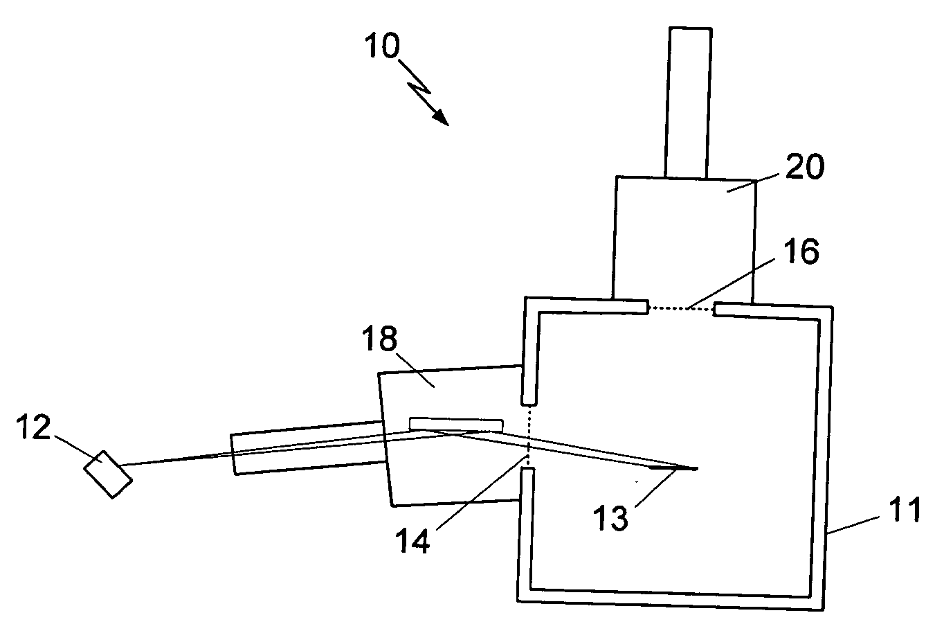
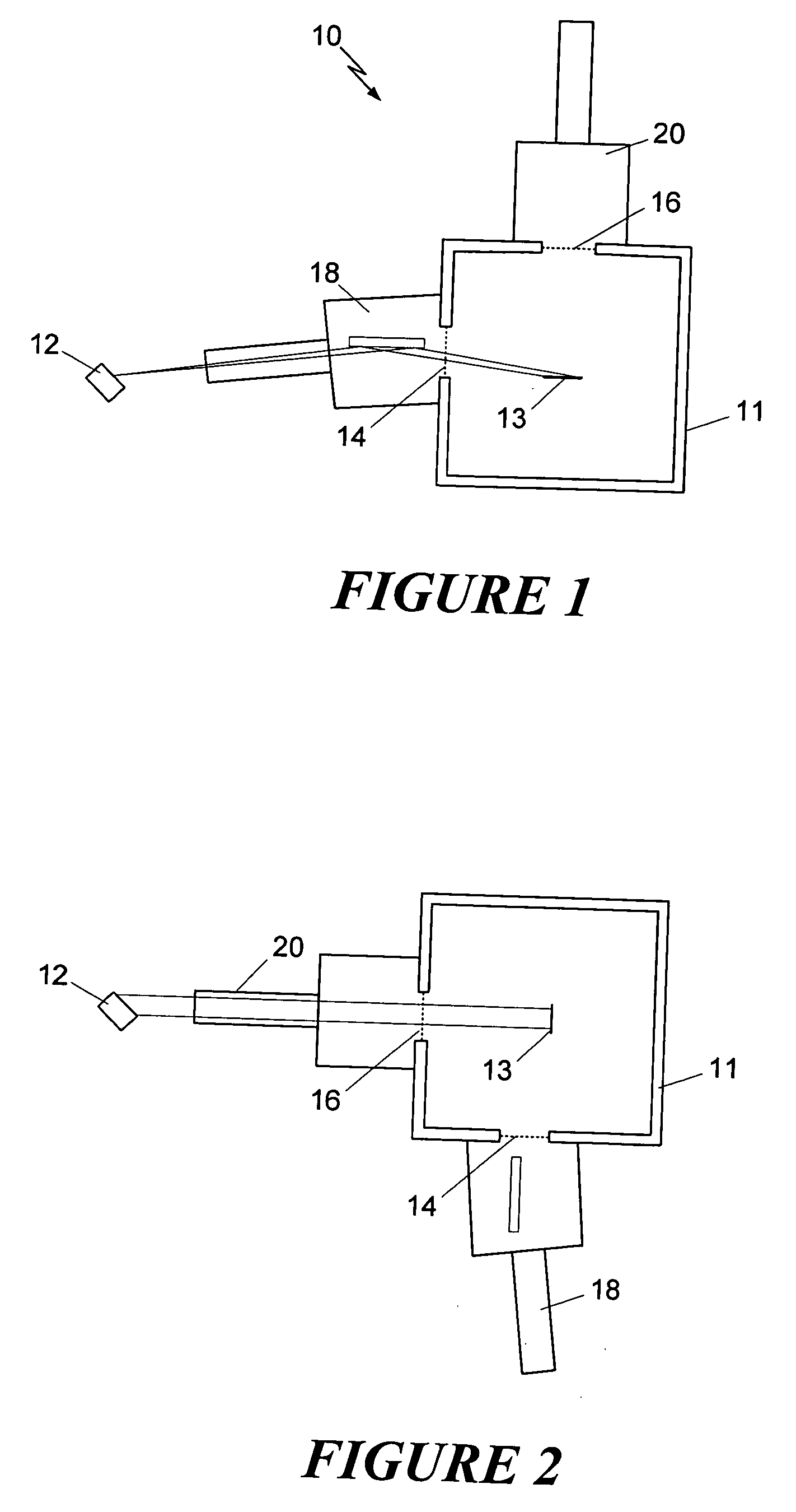
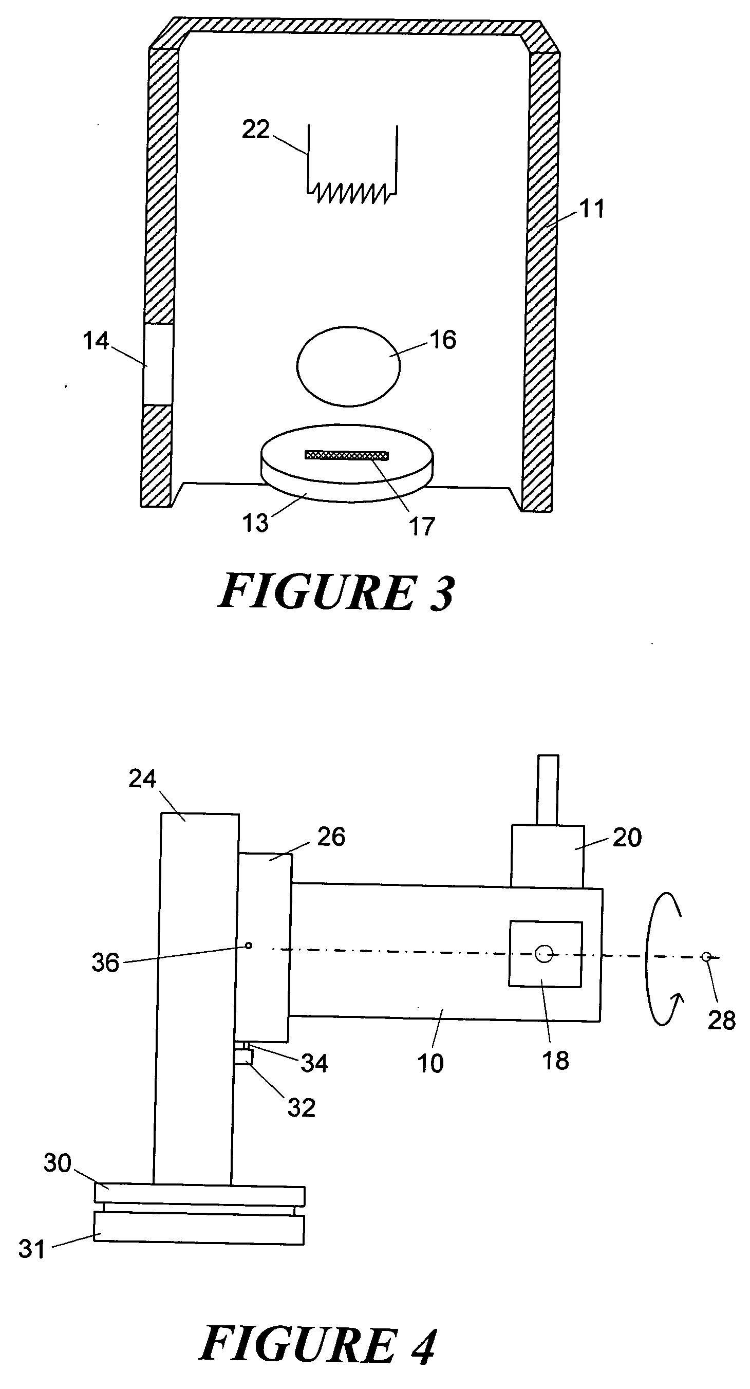
[0017] Shown schematically in FIG. 1 is a top view of an x-ray source 10 according to the present invention. The x-ray source has a housing 11 and resides adjacent to a sample 12 onto which x-ray energy is to be focused. The housing contains a conventional x-ray tube and has two ports 14, 16, via which x-ray energy may be output to the sample 12. Although all of the details of the x-ray tube are not shown in FIG. 1, the position of the target anode 13 is indicated. As in conventional systems, the anode is shaped like a line with a small finite width, and radiates in different directions, resulting in different x-ray beam cross-sections depending on the direction. Thus, for the configuration of FIG. 1, from the direction of port 14, the beam has the appearance of a spot while, from the direction of port 16, the shape of the beam is linear.

[0018] With the apparatus oriented as shown in FIG. 1, the port 16 and line focus optics are inactive. However, the port 14 and point focus optics...


PUM


Abstract

An x-ray source provides both a line focus output and a point focus output, and is mounted on a rotatable support to allow easy changing between the two. A housing has ports at different angular positions relative to an anode, and each port has an associated optic appropriate for an x-ray beam passing through that port. Three or four ports may also be used to allow for different types of beam conditioning. The different beam optics may also do conditioning based on wavelength, and the anode may be of a composite material to provide different wavelength ranges. The rotatable support may be manual or motorized, and a lockout mechanism may be used to ensure that only one port is active at a time. The support may also be located on a movable table that is movable in multiple perpendicular directions.

Description

FIELD OF THE INVENTION [0001] This invention relates generally to the field of x-ray diffraction and, more particularly, to x-ray sources used in x-ray diffraction systems. BACKGROUND OF THE INVENTION [0002] Modern x-ray diffraction experiments use x-ray tubes that are optimized to deliver a line focus or a point focus onto the sample. The optimal type of focus depends on the details of the experiment being performed. For example, for experiments involving standard powder samples, a line focus is the preferred geometry while, for two dimensional diffraction or single crystal diffraction measurements, a point focus is preferred. However, as many users may have the need to conduct experiments on different types of samples, it may be desirable to switch between point and line focus as the situation warrants. Conventionally, this is accomplished by exchanging the optics mounted on the x-ray tube. For example, a single mirror used to redirect the x-ray beam produces a line focus, and thi...

Claims


Application Information

Patent Timeline
IPC IPC(8): H01J35/00
CPCG01N2223/204H01J35/08H01J2235/081H01J35/24H01J35/18H01J35/112
Inventor DURST, ROGER D.HE, BOB BAOPING
Owner BRUKER AXS
Why Eureka
Try Eureka