A method of regulating the flow rate of air in a rotary shaft of a turbomachine

a technology of a turbomachine and a rotary shaft, which is applied in the direction of liquid fuel engines, process and machine control, instruments, etc., can solve the problems of high speed, high air flow rate, and excessive heating of certain sensitive parts of the turbomachine, so as to optimize the overall performance of the turbomachine

Active Publication Date: 2006-10-26
SN DETUDE & DE CONSTR DE MOTEURS DAVIATION S N E C M A
View PDF5 Cites 31 Cited by
  • Summary
  • Abstract
  • Description
  • Claims
  • Application Information

AI Technical Summary

Benefits of technology

[0007] A main object of the present invention is thus to mitigate such drawbacks by proposing a device for regulating the flow rate of air in a rotary shaft of a turbomachine as a function of the air requirements of the turbomachine component that is to be pressurized or cooled in order to optimize the overall performance of the turbomachine.
[0010] The use of a blade presenting bi-linear behavior gives results that are reliable in terms of opening and closing the orifice in the shaft. A blade presenting bi-linear behavior makes it possible to obtain opening and closing of the orifice in the shaft that is not progressive and proportional to the speed of rotation of the shaft, but that is substantially instantaneous at a predetermined speed of rotation of the shaft.
[0011] As a result, it is possible to trigger the opening and the closing of the orifice of the shaft solely at predetermined speeds of rotation of the shaft that correspond to operating speeds of the turbomachine for which the flow section for the air flowing in the shaft needs to be modified. Thus, the flow rate of the air flowing in the rotary shaft of the turbomachine is regulated as a function of the real requirements for air of the element of the turbomachine that is to be pressurized or cooled.
[0013] The device of the invention may further comprise an abutment element for enabling the shutter member to be held in position when it releases the orifice in the shaft.

Problems solved by technology

However, taking highly compressed air at high speed is harmful for the lifetimes of sealing systems.
It can lead to certain sensitive parts of the turbomachine being heated excessively, and that is penalizing in terms of performance.
Nevertheless, that device does not enable the flow rate of the air that is taken to be regulated as a function of the requirements for air.

Method used


Image

  • A method of regulating the flow rate of air in a rotary shaft of a turbomachine
  • A method of regulating the flow rate of air in a rotary shaft of a turbomachine
  • A method of regulating the flow rate of air in a rotary shaft of a turbomachine

Examples


Embodiment Construction

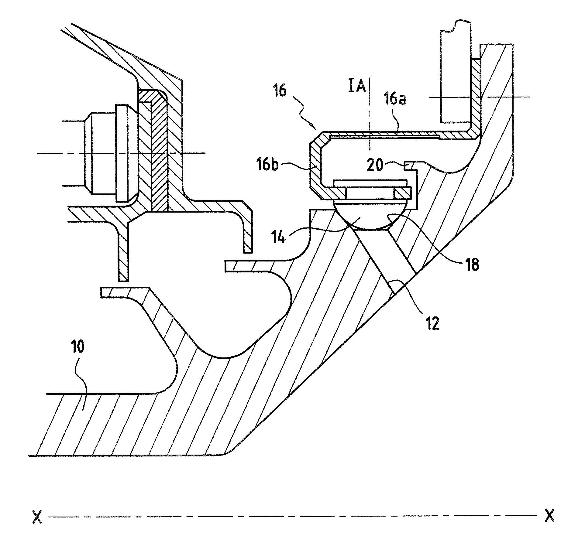
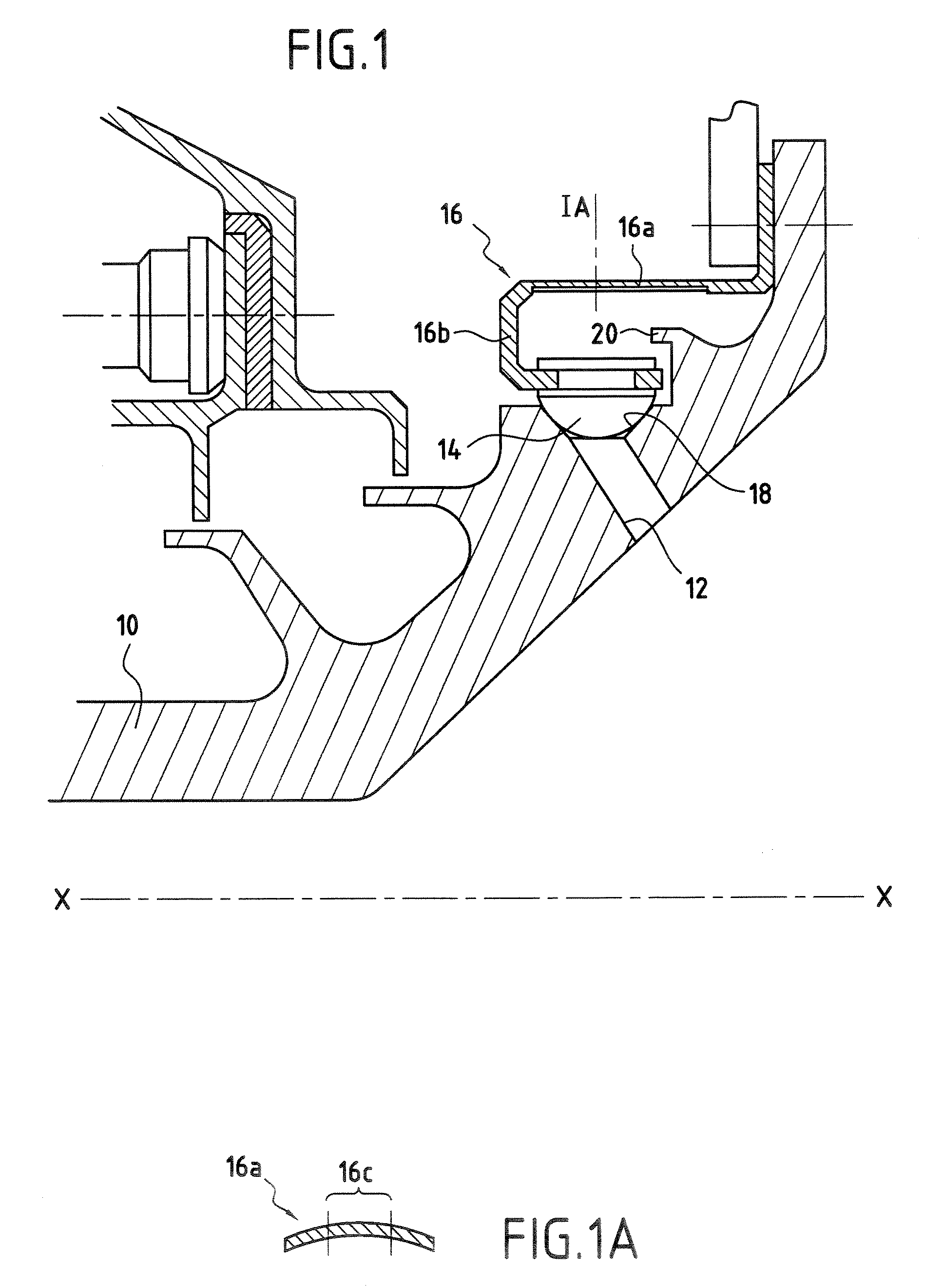
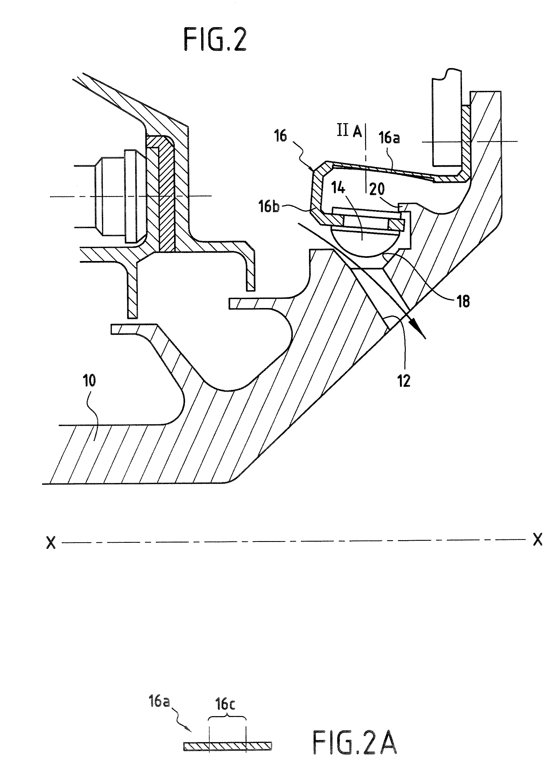
[0022]FIGS. 1 and 2 show part of a rotary shaft 10 of a turbomachine, the shaft being fitted with a device for regulating the flow rate of air that flows within the shaft.

[0023] The shaft 10 may be a high or low pressure compressor shaft of the turbomachine, or it may be a turbine shaft. The shaft 10 is centered on a longitudinal axis X-X of the turbomachine, about which it revolves.

[0024] The rotary shaft 10 is provided with at least one orifice 12 passing through it to pass air. Air that has penetrated into the shaft 10 via the orifice(s) 12 thus flows inside the shaft from upstream to downstream and / or from downstream to upstream.

[0025] The air flowing in the shaft 10 can be taken from a low-pressure compressor of the turbomachine and / or from the high-pressure compressor thereof. It may be used for pressurizing oil enclosures situated upstream or downstream in the turbomachine or for cooling certain portions of the turbomachine, for example the turbine blades.

[0026] The purpo...


PUM


Abstract

A device applied to regulating the flow rate of air flowing in a rotary shaft of a turbomachine, the shaft including at least one through orifice for passing air. The device at least one shutter member for shutting the orifice and secured to a deformable blade presenting bi-linear behavior, the blade being secured to the shaft and being suitable for deforming under the effect of the centrifugal force that results from the shaft rotating such that the shutter member is suitable for taking up two different positions depending on the speed of rotation of the shaft: one position in which it shuts the orifice; and another position in which it releases the orifice to allow air to pass through.

Description

BACKGROUND OF THE INVENTION [0001] The present invention relates to a device for regulating the flow rate of air flowing in a rotary shaft of a turbomachine, and in particular in a compressor shaft of such a turbomachine. [0002] In a turbomachine, it is common practice to take air for various purposes, in particular to regulate the pressurization of oil enclosures so as to prevent oil leaks, or to cool certain parts of the turbomachine. [0003] The functions of pressurizing and cooling these portions of the turbomachine are performed by taking air that normally comes from the high and low pressure compressors of the turbomachine, with the choice depending on the temperature and pressure conditions desired for the air that is taken. Air as taken in this way generally passes inside the shafts of the compressor or the turbine so as to be delivered to the oil enclosures for pressurizing or to the components of the turbomachine that need cooling. [0004] The taking of air from the high and...

Claims


Application Information

Patent Timeline
Patent Type & Authority Applications(United States)
IPC IPC(8): F03B11/00
CPCF01D5/08F16K31/56F04D29/584F01D17/105F04D27/0215F04D27/023Y10T137/0971
Inventor FRIEDEL, JEROME MARCELMOURLAN, JEAN-PIERRE ANDRE JOSEPHPLONA, DANIEL GEORGES
Owner SN DETUDE & DE CONSTR DE MOTEURS DAVIATION S N E C M A
Why Eureka
Try Eureka