Displacement sensor system and method of operation

a sensor and displacement technology, applied in the field of sensors, can solve the problems of increasing engine cold start-up time, reducing the work efficiency of the turbine stage, and affecting the stability of the stationary shroud,

Inactive Publication Date: 2006-10-26
GENERAL ELECTRIC CO
View PDF8 Cites 64 Cited by
  • Summary
  • Abstract
  • Description
  • Claims
  • Application Information

AI Technical Summary

Problems solved by technology

In a turbine stage, the portion of the working fluid that passes through the clearance between the tips of the turbine blades and the static shroud does no work on the rotor blades, and hence leads to a reduced work efficiency of the turbine stage.
As a result, the blades expand radially with respect to the shroud and the clearance between the shroud and the blades decreases, which may cause the interfacing surfaces of the blades and the shroud to rub, resulting in an increased engine cold start-up time.
Further, during such thermal transients, the blades expand axially with respect to the shroud, which may lead to interference of the blade tips with grooves or rails on the stationary shroud.
However, currently, clearances between the blades or seal teeth and the shroud are generally determined based on thermal models, which may often be inaccurate.
The use of models to determine clearances may result in a relatively long warm-up time before a turbine may be started because model prediction results cannot be relied on to be accurate.
Further, no technique currently exists to measure axial clearance at the turbine stages.
The above technique may prove ineffective because growth of individual stages need not be essentially linear due to bulk of material distributed around certain stages form a bigger thermal sink than the rest of the engine.

Method used


Image

  • Displacement sensor system and method of operation
  • Displacement sensor system and method of operation
  • Displacement sensor system and method of operation

Examples


Embodiment Construction

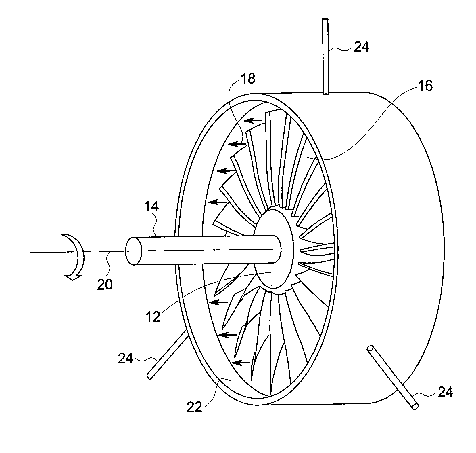
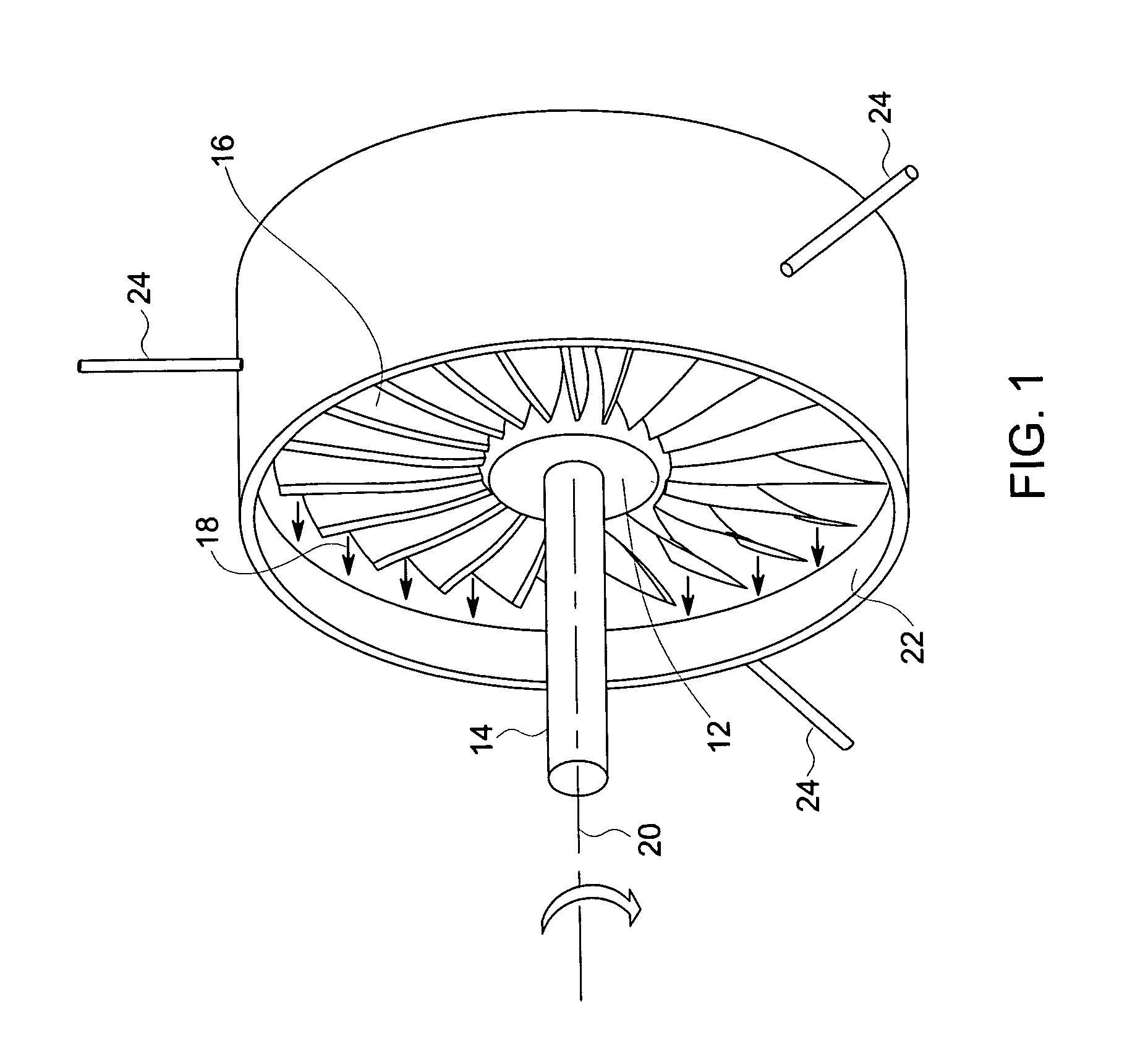
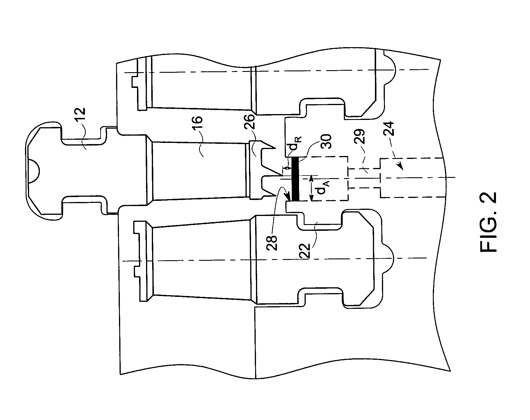
[0021] The following description presents a novel technique for measuring axial displacements as well as radial clearances between rotating and stationary components in a rotating machine. For example, the present technique may find application in a steam turbine to measure radial and axial displacements of the rotating blades or the seal teeth with respect to the surrounding stationary shroud. In one embodiment of the present technique, radial and axial displacements are sensed by measuring a capacitance between the tips of the rotating blades or seal teeth and one or more sensors disposed on the shroud. The displacements thus measured may then be incorporated into a control strategy to insure that that there is no rub or interference due to thermal growth in both radial and axial directions between the rotating and static parts during operation of the turbine. Advantageously, the technique described facilitates an in situ real time measurement of axial and radial displacement at a...


PUM


Abstract

A clearance sensing system for a rotating machine includes a plurality of sensor probes disposed within a stationary shroud of the rotating machine. Each of the plurality of sensor probes is adapted to measure a parameter indicative of an axial and a radial displacement of a rotating component within the shroud and to produce a signal that corresponds to the parameter. In certain embodiments, this parameter may include a capacitance between the rotating component and the sensor probe. The clearance sensing system further includes a circuit that receives the signal from each of the plurality of sensor probes and determines (a) the axial displacement of the rotating component within the shroud and (b) a radial displacement of the rotating component relative to the shroud.

Description

BACKGROUND [0001] The invention relates generally to the field of sensors, and particularly to sensors for measuring relative displacement between rotating and moving components in a rotating machine. Specific embodiments of the present technique provide a system and method for sensing radial clearance and relative axial displacement of the rotating components, such as blades and seal tips with respect to the stationary shroud in a turbine engine. [0002] Efficiency and performance of gas and steam turbines are affected by clearances between tips of the rotating blades and the stationary shrouds. In a turbine stage, the portion of the working fluid that passes through the clearance between the tips of the turbine blades and the static shroud does no work on the rotor blades, and hence leads to a reduced work efficiency of the turbine stage. Hence, in the design of gas and steam turbines, it is desirable to have a close tolerance between the tips of the rotor blades and the surroundin...

Claims


Application Information

Patent Timeline
Patent Type & Authority Applications(United States)
IPC IPC(8): F04D29/66
CPCF01D11/08F01D21/003F05D2260/85F04D27/001G01B7/144F01D21/04
Inventor SHAH, MINESH ASHOKBALASUBRAMANIAM, MAHADEVANBEAUCHAMP, PHILIP PAULANDERSON, TODD ALANDASGUPTA, SAMHITASHADDOCK, DAVID MULFORDANDARAWIS, EMAD ANDARAWIS
Owner GENERAL ELECTRIC CO
Why Eureka
Try Eureka