High stiffness, high accuracy, parallel kinematic, three degree of freedom motion platform

a motion platform and high accuracy technology, applied in the field of parallel kinematic machines (p), can solve the problem of not being able to tolerance the joint that mounts the driven components, and achieve the effect of wide range of positions and higher stiffness and/or accuracy

Inactive Publication Date: 2006-10-26
NAT RES COUNCIL OF CANADA
View PDF26 Cites 28 Cited by
  • Summary
  • Abstract
  • Description
  • Claims
  • Application Information

AI Technical Summary

Benefits of technology

[0011] Accordingly a PKM is provided that controls a motion platform, providing higher stiffnesses and / or accuracies at a wider range of positions and orientations.

Problems solved by technology

Furthermore, as the driven components are statically held by the base structure, there is no tolerance of a joint that mounts the driven components to the support structure to contend with.

Method used


Image

  • High stiffness, high accuracy, parallel kinematic, three degree of freedom motion platform
  • High stiffness, high accuracy, parallel kinematic, three degree of freedom motion platform
  • High stiffness, high accuracy, parallel kinematic, three degree of freedom motion platform

Examples


Embodiment Construction

[0033] The invention provides a Parallel Kinematic Machine (PKM) for controlling position and orientation of a motion platform that provides improvements in stiffness and accuracy throughout a wider range of motions, positions and orientations than provided in the prior art, with lower cost and lower stiffness kinematic links.

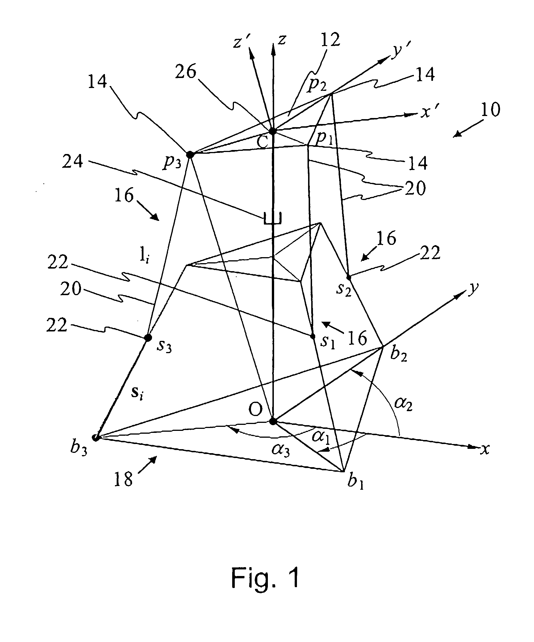
[0034]FIG. 1 is a static vector diagram of a PKM 10 in accordance with an embodiment of the invention for controlling position and orientation of a motion platform 12. At each of three (preferably maximally separated) points (p1, p2, p3) on the motion platform 12, there is a corresponding spherical joint 14 which serves to couple the motion platform 12, via a respective kinematic chain 16, to a base 18. Each kinematic chain 16 includes: a sliding, fixed-length leg 20 coupled at one end to the motion platform 12 by the spherical joint 14 at a corresponding point pi, and at an opposite end, by a universal joint 22 that is constrained to move along a respective g...


PUM


Abstract

A parallel kinematic machine (PKM) with three active kinematic chains and a leg has improved precision and stiffness maps by: providing drive and actuation of each active kinematic chain by devices secured rigidly to a support structure so that only a fixed length leg of the chain is suspended; driving the fixed length leg of the active kinematic chain to move in a direction oblique to a direction of the fixed length leg; and providing a prismatically jointed leg that is rigidly secured to the base structure and coupled by an effectively universal joint to the motion platform.

Description

[0001] This application claims benefit of U.S. Provisional Patent Application 60 / 672,854 filed Apr. 20, 2005.FIELD OF THE INVENTION [0002] This invention relates in general to Parallel Kinematic Machines (PKM) for precision machining, motion, locating, positioning, fixturing, and more particularly to a PKM for use in a machine having greater stiffness and accuracy when subjected to greater loads. BACKGROUND OF THE INVENTION [0003] Kinematic chains that control position and orientation of a motion platform (typically an adapter for coupling to one or more tools or fixtures) to a rigid support in use today are typically serial jointed mechanisms. For example, conventional orthogonal multi-axis machines are known that control motion of the platform with three degrees of freedom, have three axes arranged as three mutually orthogonal beams. One axis is laid upon the other serially. Unfortunately the inertia of a tool supported by a multi-axis machine is generally large because of the dis...

Claims


Application Information

Patent Timeline
Patent Type & Authority Applications(United States)
IPC IPC(8): G06F19/00
CPCB25J17/0266
Inventor ZHANG, DANLANG, SHERMAN Y. T.ORBAN, PETERBI, ZHUMINGVERNER, MARCELKOWALA, STANKINGSTON, DAVID W.
Owner NAT RES COUNCIL OF CANADA
Why Eureka
Try Eureka