Logon system for an electronic device

Inactive Publication Date: 2006-10-26
KINPO ELECTRONICS
View PDF1 Cites 24 Cited by
  • Summary
  • Abstract
  • Description
  • Claims
  • Application Information

AI Technical Summary

Benefits of technology

[0006] The object of the invention is to provide an unconventional logon system in term of software and har

Problems solved by technology

In this way, a traditional key-logging typed cracking will not be su

Method used


Image

  • Logon system for an electronic device
  • Logon system for an electronic device
  • Logon system for an electronic device

Examples


Example

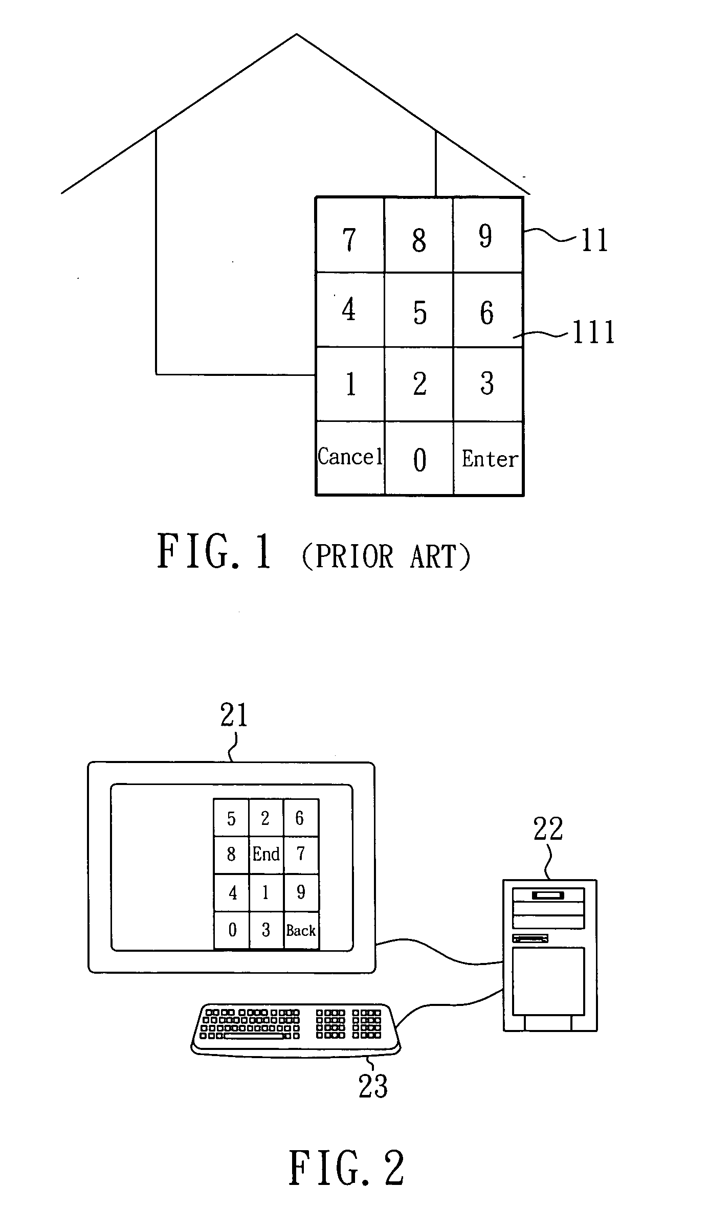
[0016]FIG. 2 is a diagram of a configuration of a logon system for an electronic device according to the invention. The system has an input device 23, a display 21 and an electronic device 22. The input device 23 can be a keyboard or mouse to control cursor positions displayed on the display 21 and to input the information of digits or characters to the electronic device 22. The display 21 is an LCD, CRT or touch display connected to the electronic device 22 and can function as an input and output device of the electronic device 22. Namely, the electronic device 22 can display information on the display 21, and when the touch display is used, a user can touch the touch display to input the information to the electronic device 22.

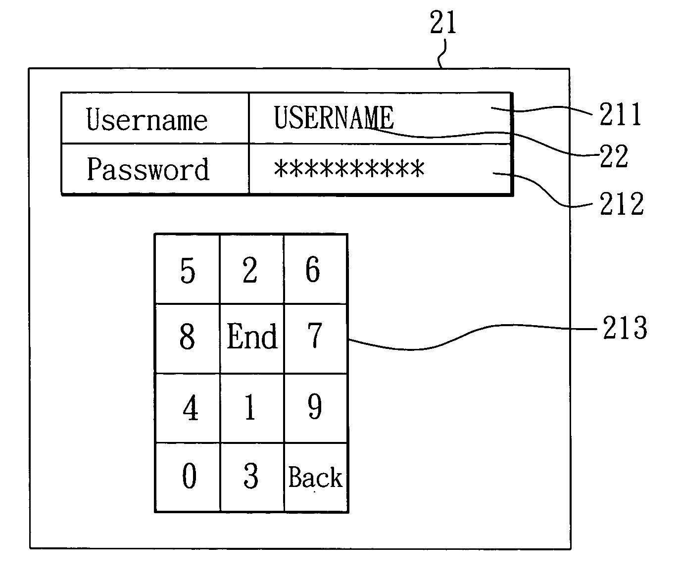
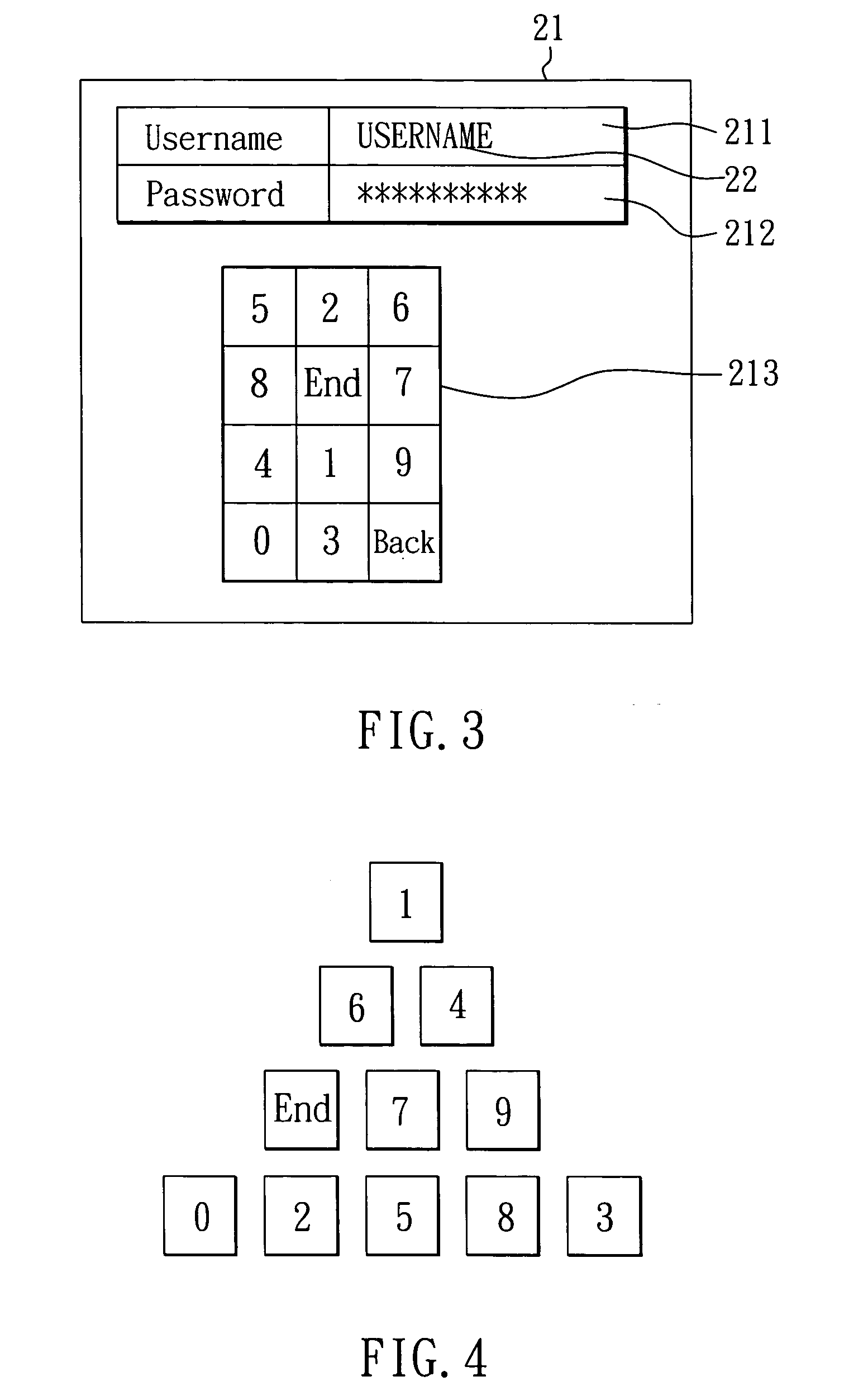
[0017] As shown in FIG. 3, when the user is to log on the electronic device 22, the electronic device 22 displays a username field 211 and a password field 212 on the display 21 and presents an input cursor 22 at the username field 211. The user first uses ...


PUM


Abstract

A logon system for an electronic device is provided. The system includes an electronic device and a touch display. The touch display is connected to the electronic device for functioning as an input/output device of the electronic device. For a logon to the electronic device, the electronic device displays a keypad having multiple keys on the touch display, and an arrangement of the keys is determined by the electronic device in random, so that a user can log on the electronic device by touching the keys displayed on the touch display.

Description

BACKGROUND OF THE INVENTION [0001] 1. Field of the Invention [0002] The invention relates to a logon system for an electronic device. [0003] 2. Description of Related Art [0004] For a traditional logon of an electronic device such as a computer, terminal, automatic teller machine or entrance guard, as shown in FIG. 1, a password is initially input through a 11 Keys's keypad and the key-in password will then be shown as asterisks on the respective devices' screens. However, this act may lead the user's finger prints remain on the keypad and eventually provides a trace for the password breaking. A classic password crack would be simply uncovering by a finger prints scan. [0005] In addition, when the password is input through a Trojan horse or Key-logging infected computer and which is also connected with an unsecured network, a genuine password will be at the great risk of interception or replicating. Of course, this situation only happens if the computer is virus infected. A known Tr...

Claims


Application Information

Patent Timeline
IPC IPC(8): G06F12/14H04L9/00G06F17/30H04K1/00G06F12/00G06F13/00G06F7/04G06F7/58G06K19/00G11C7/00H04L9/32
CPCG06F21/36
Inventor HSU, HO-HSIUNG
Owner KINPO ELECTRONICS
Why Eureka
Try Eureka