Saw chains having hardened cutting elements and methods for production thereof

a technology of cutting elements and saw chains, applied in the field of saw chains, can solve the problems of affecting the requiring frequent sharpening, and affecting the cutting quality of saw chains, and achieving the effect of reducing the number of saw chains

Inactive Publication Date: 2006-11-02
UNIFIRE POWER BLOWER
View PDF20 Cites 23 Cited by
  • Summary
  • Abstract
  • Description
  • Claims
  • Application Information

AI Technical Summary

Benefits of technology

[0010]FIG. 2 is a side view showing a segment of a conventional saw chain as known in the prior art.

Problems solved by technology

As a chain saw is used, the cutting members of the saw chain will typically wear down quickly and require frequent sharpening.
It is a much greater problem when cutting harder materials.
Even the mere striking of nails or screws while cutting through wooden wall or floor structures is very derogatory and can immediately dull a saw chain.
Unfortunately, the cutting members of conventional saw chains tend to become dull quickly under easy conditions in wood, and they dull extremely fast when materials other than wood are encountered.
These saw chains have satisfied some of the aforementioned needs, but unfortunately the production of such saw chains requires expensive production techniques, such as manually affixing of each cutting element.
Such saw chains are also expensive to maintain due to frequent breakage of the hardened cutting elements.
Breakage and dislodgement of the hardened cutting elements has severely impeded their acceptance in the market for saw chains.

Method used


Image

  • Saw chains having hardened cutting elements and methods for production thereof
  • Saw chains having hardened cutting elements and methods for production thereof
  • Saw chains having hardened cutting elements and methods for production thereof

Examples


example a

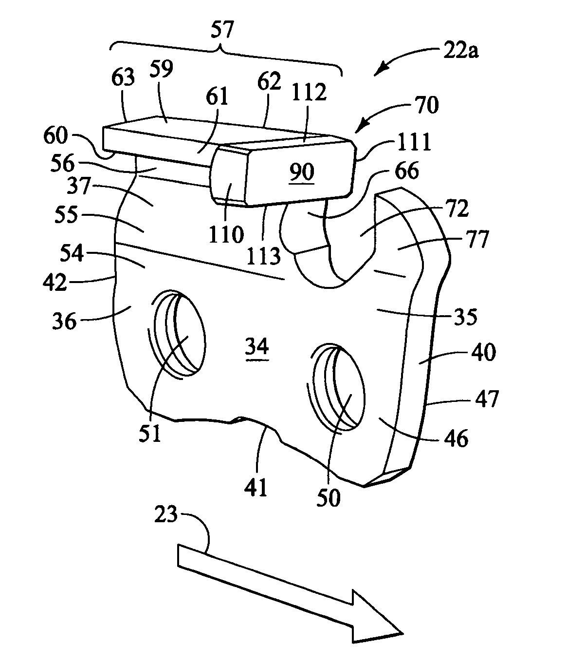
[0072] The tri-metal shim consists of silver solder copper and then another layer of silver solder. The shim is formed in a die to the outer shape of the cylindrical portion of the carbide insert. It is then attached to the carbide insert by induction welding or baked to a temperature that allows the silver solder to flow only on one side, then cooled. The carbide is then set in a jig manually that holds the carbide in place next to the chassis where it is reheated and welded in place by flame welding (gas).

example b

[0073] The tri-metal shim consists of silver solder, copper, and then another layer of silver solder. The shim is formed in a die to the outer shape of the cylindrical portion of the carbide insert. It is then attached to the carbide insert by induction welding or baked to a temperature that allows the silver solder to flow only on one side, then cooled. The carbide pieces are put in a vibratory shaker and sorted where they then slide down into a fixture that holds the carbide in place next to the chain chassis and heated by means of induction welding or flame welding (gas). The chain automatically advances to the next position and the next piece of carbide is indexed into place and welded.

[0074] The carbide inserts are set in place by a mechanical means in which it is automated and does not require any application of manual labor.


PUM

PropertyMeasurementUnit
filing angleaaaaaaaaaa
rake anglesaaaaaaaaaa

Abstract

Hardened cutter elements commonly called cutters used in saw chains to act as cutter links. The hardened cutters have hard insets applied and connected to the cutting face of the cutter. The insets are made of a hard, tough material, such as a suitable carbide. Also shown are saw chains having the hardened cutter links with the hard insets. The preferred insets include a rear portion having a semi-cylindrical attachment surface. The attachment surface is configured for attachment to a filed or ground cutting face of a conventional saw chain cutter. A front portion of the inset has a cutting face which is provided with beveled cutting face corners and preferably chamfered edges extending rearwardly from the inset cutting face. Methods of producing the cutters with insets and for producing saw chains with the hardened cutters are also described.

Description

TECHNICAL FIELD [0001] The present invention relates to saw chains used on chain saws having hardened cutting elements and related methods, such as methods for producing such saw chains and components thereof. BACKGROUND OF THE INVENTION [0002] Chain saws are commonly used for cutting wood. Although chain a saws are frequently used for the cutting of wood, they are also used to perform many other cutting tasks. For example, chain saws can be used for cutting other materials. In some applications, such as firefighting, it is common for chain saws to be used for cutting wood, nails, metals, concrete, tile, and other relatively hard materials in an emergency situation. These hard materials are encountered when a chain saw is used to cut through floors, walls or other structural components in responding to a fire. [0003] As a chain saw is used, the cutting members of the saw chain will typically wear down quickly and require frequent sharpening. This is true even with relatively soft ma...

Claims


Application Information

Patent Timeline
Patent Type & Authority Applications(United States)
IPC IPC(8): B23D63/00B27B33/14
CPCB27B33/144Y10T407/23B28D1/124Y10T83/921Y10T83/9319Y10T83/913Y10T83/909
Inventor RACZYKOWSKI, DANIEL G.
Owner UNIFIRE POWER BLOWER
Why Eureka
Try Eureka