Transfer method and transfer apparatus

a transfer method and transfer apparatus technology, applied in the direction of dye addition to spinning solution, coating, printing, etc., can solve the problems of large size, foreign substances may enter the vacuum chamber, damage to the donor substrate, etc., and achieve the effect of reducing the capacity and simplifying the structure of the vacuum chamber

Inactive Publication Date: 2006-11-02
SONY CORP
View PDF4 Cites 89 Cited by
  • Summary
  • Abstract
  • Description
  • Claims
  • Application Information

AI Technical Summary

Benefits of technology

[0018] In this transfer apparatus, the vacuum chamber is required to have only a space in which the receptor substrate and the donor substrate are stacked. Therefore, unlike the known contact transfer apparatus, it is unnecessary to provide movable holding members that are used to stack the receptor substrate and the

Problems solved by technology

For this reason, the vacuum chamber has a complicated structure and a large size.
Moreover, foreign substances may enter or the donor substrate may be damaged when the d

Method used


Image

  • Transfer method and transfer apparatus
  • Transfer method and transfer apparatus
  • Transfer method and transfer apparatus

Examples


Embodiment Construction

[0025] An embodiment of the present invention will be described in detail below with reference to the drawings.

Receptor Substrate

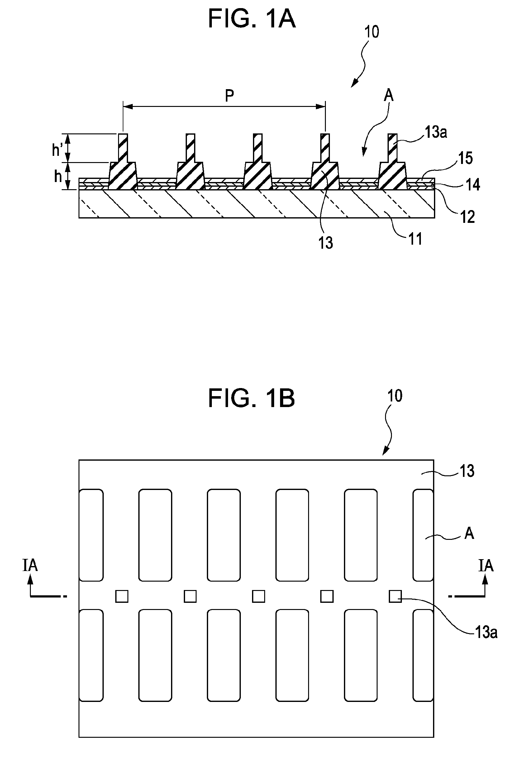
[0026] First, a receptor substrate will be described. FIGS. 1A and 1B are an enlarged cross-sectional view and an enlarged plan view, respectively, showing the principal part of a receptor substrate 10 used in an embodiment of the present invention. FIG. 1A is a cross-sectional view taken along line IA-IA in FIG. 1B.

[0027] As shown in FIG. 1A, TFTs (thin film transistors) (not shown) are formed on a base 11 made of, for example, glass, and a plurality of lower electrodes (positive electrodes) 12 made of, for example, chromium (Cr) are then patterned thereon corresponding to sub-pixels A while an interlayer insulating film is provided between the TFTs and the lower electrodes 12. Subsequently, for example, a polyimide film is formed to cover the lower electrodes 12, and an insulating layer 13, which is shaped like a lattice in plan view, is then formed ...


PUM

PropertyMeasurementUnit
Thicknessaaaaaaaaaa
Sizeaaaaaaaaaa

Abstract

A transfer method includes the steps of placing a donor substrate including a support base and a transfer layer provided on the support base onto a receptor substrate such that the transfer layer faces the receptor substrate, evacuating a space between the receptor substrate and the donor substrate that are placed one on the other, and transferring the transfer layer onto the receptor substrate by applying a radiant ray onto the donor substrate in an evacuated atmosphere.

Description

CROSS REFERENCES TO RELATED APPLICATIONS [0001] The present invention contains subject matter related to Japanese Patent Application JP 2005-128908 filed in the Japanese Patent Office on Apr. 27, 2005 and Japanese Patent Application JP 2005-168018 filed in the Japanese Patent Office on Jun. 8, 2005, the entire contents of which are incorporated herein by reference. BACKGROUND OF THE INVENTION [0002] 1. Field of the Invention [0003] The present invention relates to a transfer method and a transfer apparatus used in the method, and more particularly, to a transfer method and a transfer apparatus for thermally transferring a luminescent layer of an organic electroluminescence (EL) device. [0004] 2. Description of the Related Art [0005] In a full-color display device, organic electroluminescent devices corresponding to colors of R (red), G (green), and B (blue) are arranged on a substrate. In this display device, it is necessary at least to pattern luminescent layers corresponding to th...

Claims


Application Information

Patent Timeline
IPC IPC(8): B44C1/17
CPCB44C1/17H05B33/10
Inventor MATSUO, KEISUKEMATSUDA, EISUKE
Owner SONY CORP
Why Eureka
Try Eureka