Liquid-cooled semiconductor unit for cooling high-power semiconductor elements that are enclosed in modules

Inactive Publication Date: 2006-11-02
DENSO CORP
View PDF18 Cites 57 Cited by
  • Summary
  • Abstract
  • Description
  • Claims
  • Application Information

AI Technical Summary

Benefits of technology

[0021] From another aspect of the invention, the coolant discharge header preferably contains a coolant discharge passage having a cross-sectional area that is larger than the cross-sectional area of a coolant supply flow passage within the coolant supply header. This provides the advantage that vapor bubbles which are generated within the flow paths in the cooling tubes will rise into a region of relatively cool liquid within the coolant discharge passage, and so will be rapidly condensed back to liquid form.
[0022] From a further aspect, each of the cooling tubes is preferably formed internally with a plurality of cooling fins, i.e., located within the coolant flow passage of said cooling tube. This serves to increase the effective area of contact between the cooling tubes and the liquid coolant, thereby enhancing the heat exchange efficiency of the unit.
[0023] With such a configuration, the coolant supply h

Problems solved by technology

Due to the large current that must be fed by these semiconductor elements, the semiconductor modules generate large amounts of heat.
With such a type of liquid-cooled semiconductor unit, the following problems arise.
However this has proven difficult, with possible air bubbles being left within the cooling tubes

Method used


Image

  • Liquid-cooled semiconductor unit for cooling high-power semiconductor elements that are enclosed in modules
  • Liquid-cooled semiconductor unit for cooling high-power semiconductor elements that are enclosed in modules
  • Liquid-cooled semiconductor unit for cooling high-power semiconductor elements that are enclosed in modules

Examples


first embodiment

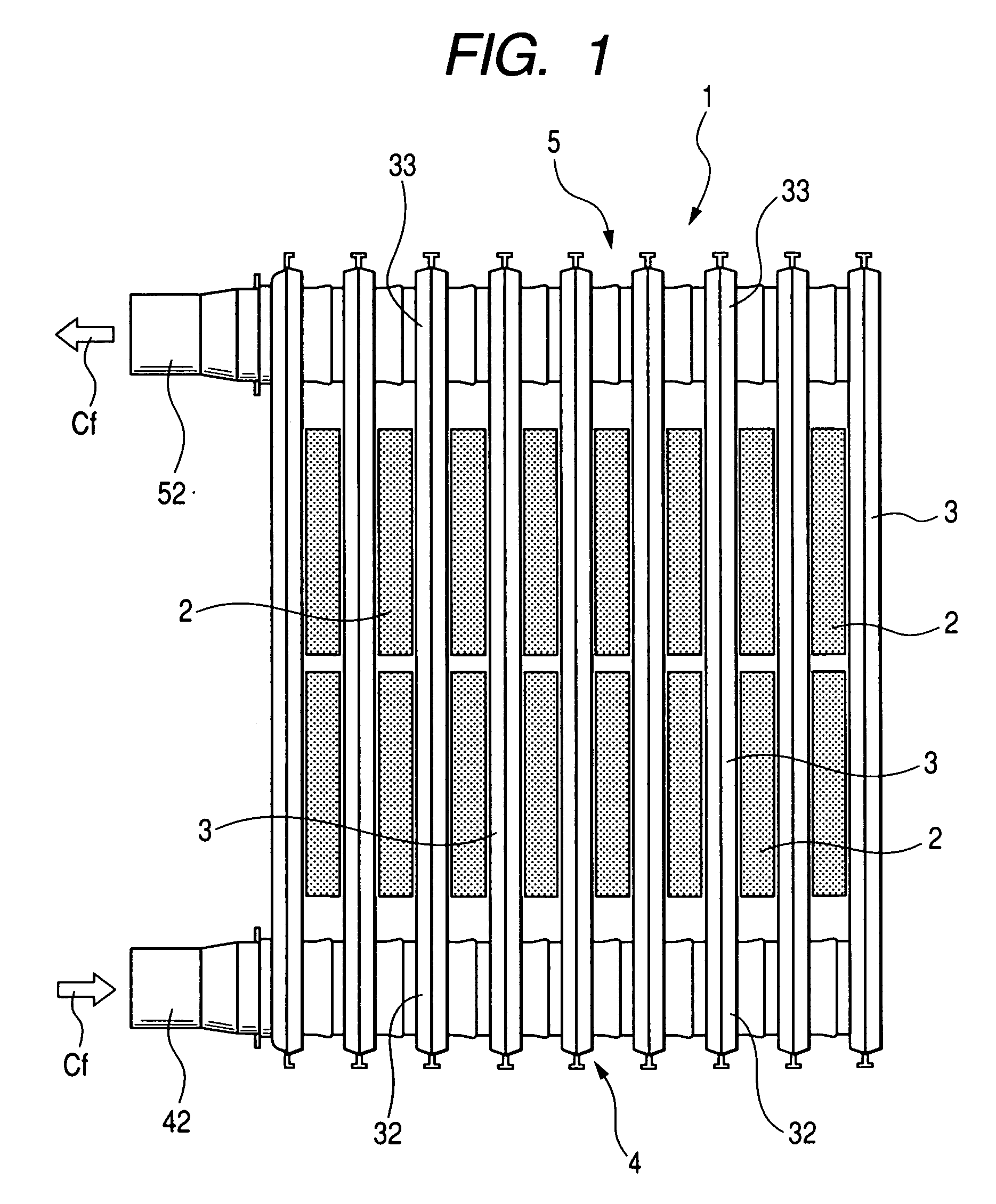
[0031] A first embodiment of a liquid-cooled semiconductor unit (referred to in the following simply as a cooled semiconductor unit) will be described referring to FIGS. 1 to 5. FIGS. 3 to 5 are simplified conceptual cross-sectional diagrams, provided for describing the advantageous effects obtained by the first embodiment.

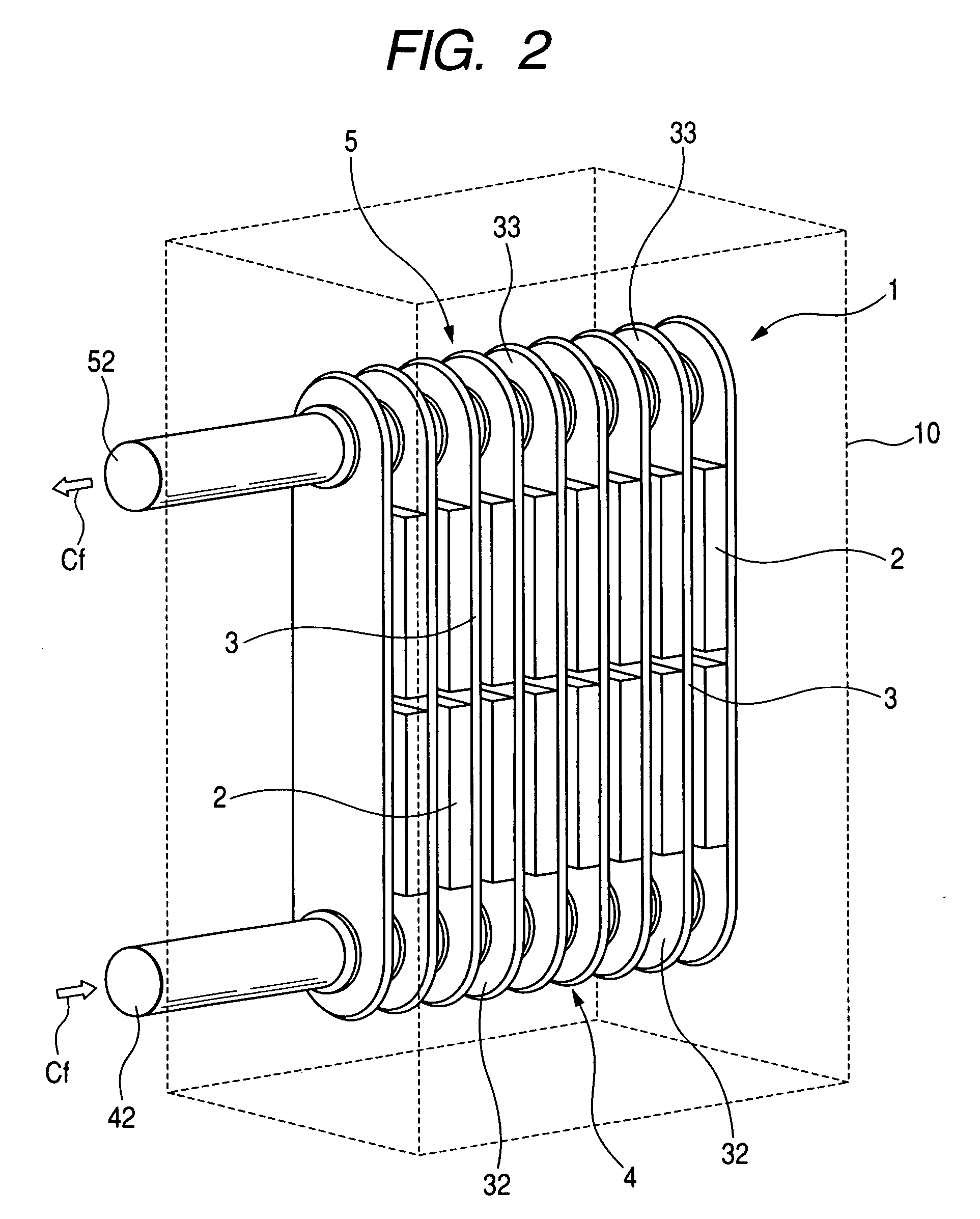
[0032] As shown in FIGS. 1 to 3 the cooled semiconductor unit, designated by reference numeral 1, includes a plurality of semiconductor modules 2 (each having one or more semiconductor elements internally contained therein), and a plurality of cooling tubes 3 which are arrayed in parallel, with each of the semiconductor modules 2 being sandwiched between two of the cooling tubes 3 as shown.

[0033] A coolant supply header 4 of the cooled semiconductor unit 1 is connected to the respective intake end apertures 32 of the cooling tubes 3, with a coolant supply passage 41 within the coolant supply header 4 communicating with (i.e., opening into) respective coolant flo...

second embodiment

[0055] A second embodiment of a cooled semiconductor unit will be described, in which the coolant supply flow passage 41 and coolant discharge passage 51 of a cooled semiconductor unit 100 are formed with respective upwardly (i.e., upward with respect to the flow direction of the coolant Cf) sloping portions 61a, 61b (i.e., such as to produce an upward-sloping direction of flow of the coolant Cf) as shown in the conceptual cross-sectional view of FIG. 6. Alternatively stated, each of the portions 61a of the coolant supply flow passage 41 and portion 61b of the coolant discharge passage 51 is directed upward along the downstream direction of flow of the coolant Cf.

[0056] In other respects, the operation and configuration of this embodiment are similar to those of the first embodiment described above, with reference numerals in FIG. 6 designating components that have similar functions to the correspondingly numbered components of the first embodiment.

[0057] However with the second e...

third embodiment

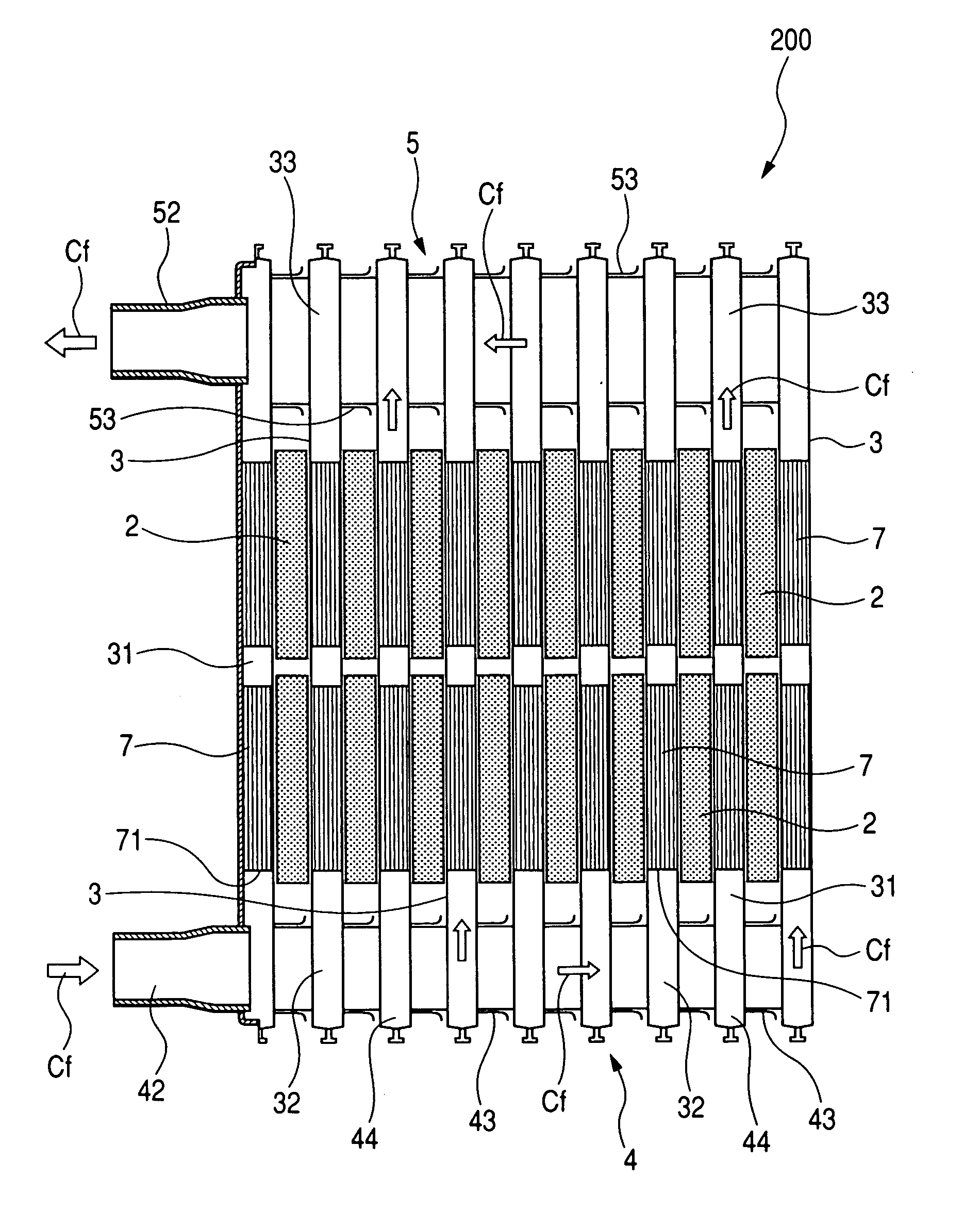
[0058] A third embodiment will be described referring to FIG. 7, which is a cross-sectional diagram taken in elevation of a cooled semiconductor unit 200.

[0059] With this embodiment, for ease of manufacture, each of the intake end aperture portions 32 has coupling tubes 43 formed thereon, adapted to enable the coupling tubes of adjacent outlet end aperture portions 33 to be joined together. In that way as can be readily understood from FIG. 7, the coolant supply header 4 is constituted by the set of intake end aperture portions 32 and their coupling tubes, in combination. Similarly, each of the outlet end aperture portions 33 has coupling tubes 53 formed thereon, with the coolant discharge header 5 being constituted by the set of intake end aperture portions 32 and their coupling tubes 53, in combination.

[0060] A first distinguishing feature of this embodiment is that the cross-sectional area of the flow passage within the coolant discharge header 5 (corresponding to the coolant d...


PUM


Abstract

In a liquid-cooled semiconductor unit having one or more semiconductor modules and a plurality of cooling tubes arrayed in parallel, with each semiconductor module sandwiched between a pair of cooling tubes, a coolant supply header for supplying a flow of liquid coolant through respective flow passages in the cooling tubes and a coolant discharge header for discharging the liquid coolant from these coolant flow passages, each of the cooling tubes is disposed with an outlet end aperture portion thereof located at a higher elevation than an intake end aperture portion thereof.

Description

CROSS-REFERENCE TO RELATED APPLICATIONS [0001] This application is based on and incorporates herein by reference Japanese Patent Application No. 2005-132386 filed on Apr. 28, 2005 and Japanese Patent Application No. 2006-063768 filed on Mar. 9, 2006. BACKGROUND OF THE INVENTION [0002] 1. Field of Application [0003] The present invention relates to a liquid-cooled semiconductor unit having one or more semiconductor modules, each enclosing one or more semiconductor elements, and a plurality of cooling tubes through which a liquid coolant flows for cooling the semiconductor modules and thereby cooling the semiconductor elements. [0004] 2. Description of Related Art [0005] Power conversion devices such as DC-DC converters, power inverters, etc., are used, for example, to supply drive current to an AC motor that serves as a motive power in an electric vehicle or hybrid electric type of vehicle (i.e., which can be driven by an internal combustion engine and / or AC motor). In such an applic...

Claims


Application Information

Patent Timeline
IPC IPC(8): H05K7/20
CPCH01L23/473H01L2924/0002H01L2924/00
Inventor SAKAI, YASUYUKINARUMI, YUKITOSHIKAKO, HIROFUMI
Owner DENSO CORP
Why Eureka
Try Eureka