

Ultrasonic float-up device
a technology of ultrasonic levitation and float device, which is applied in the direction of magnetic holding device, generator/motor, instruments, etc., can solve the problems of spoiling the stability of movement, and achieve the effect of effective handling precision positioning
- Summary
- Abstract
- Description
- Claims
- Application Information
AI Technical Summary
Benefits of technology
Problems solved by technology
Method used
Image

Examples
first embodiment
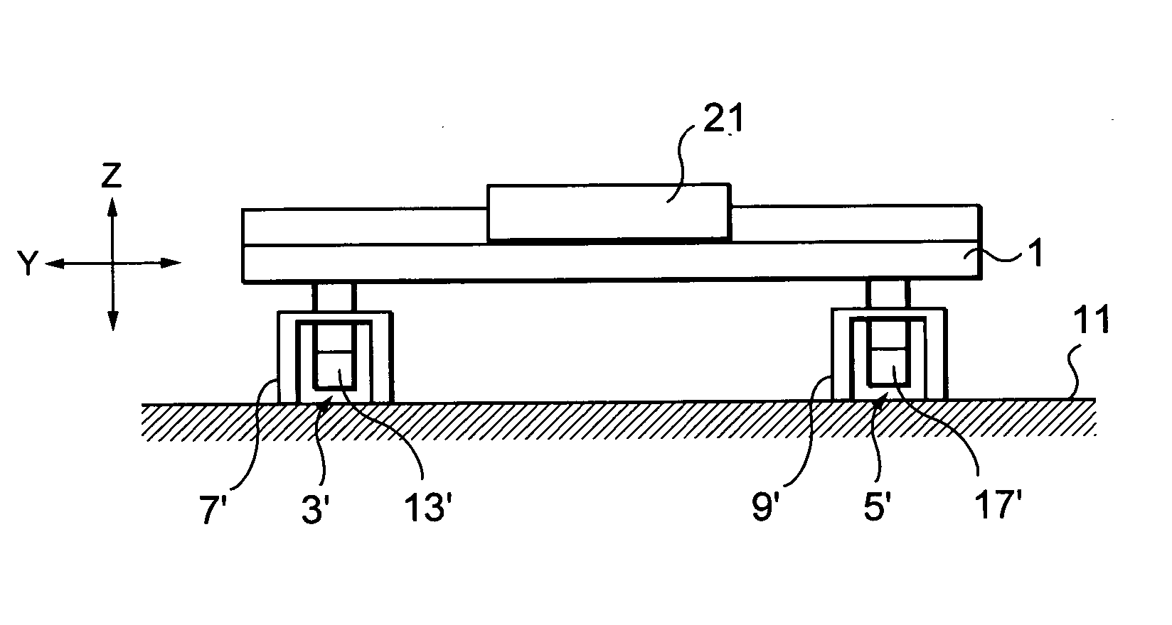
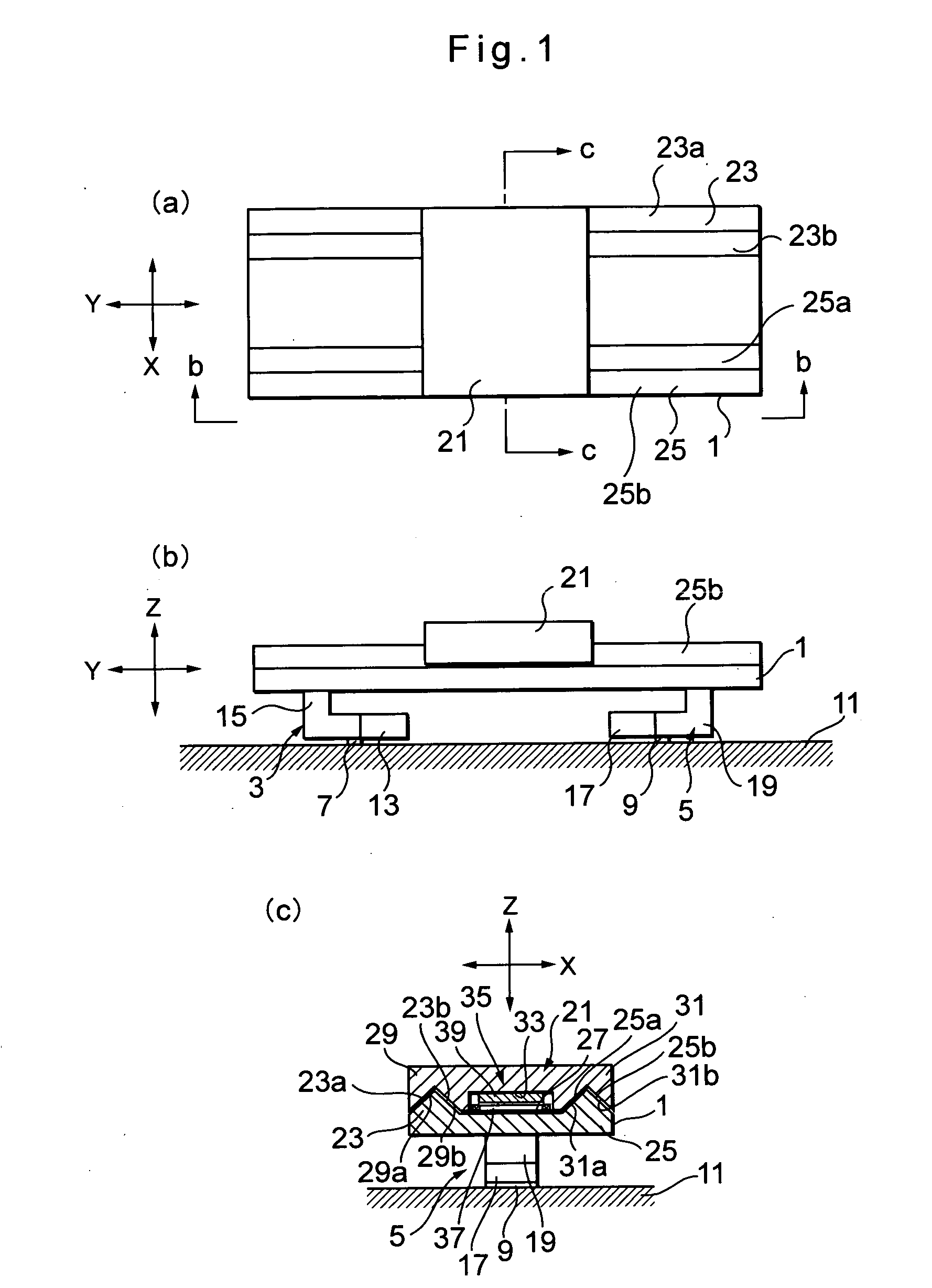
[0040] the present invention will be explained with reference to FIGS. 1 through 5. FIG. 1 has several views showing a structure of a first embodiment of the present invention, wherein FIG. 1 (a) is a plan view of an ultrasonic levitation device, Fig. 1 (b) is a view as seen by the arrows b-b of FIG. 1 (a), and FIG. 1 (c) is a sectional view cut along the line c-c of FIG. 1 (a).
[0041] There is a fixed section 1 in a flat panel shape. There are also vibration generating devices 3, 5, respectively attached to the left end part and the right end part in the elongating direction, on the bottom surface of the fixed section 1. There are supporting members 7, 9, respectively attached to the vibration generating devices 3, 5, whereby the fixed section 1 is mounted on a base 11 via the supporting members 7, 9.
[0042] The vibration generating device 3 comprises a Langevin type ultrasonic transducer 13 and an L-shaped vibration direction converting member 15. Similarly, the vibration generatin...
third embodiment
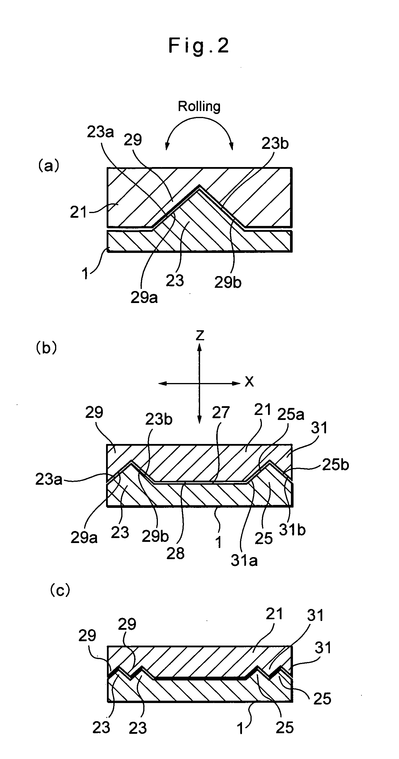
[0080] although there is only single set of substantially isosceles trapezoidal concave and convex guides provided as an example, it is also possible to provide two or more sets of these concave-convex guides.
[0081] Now a fourth embodiment of the present invention will be explained with reference to FIG. 8. Referring back to FIG. 7, the third embodiment has the structure in which the pair of fixed section-side guides 105, 107, and the pair of cross-shaped vibration converting members 121, 125 have been assembled. In such structure, the assembling dimensional accuracy of the fixed section 101 is determined by the sum of dimensional accuracy and the sum of the assembling dimensional error of each element, i.e. the fixed section-side guides 105, 107 and the cross-shaped vibration converting members 121, 125.
[0082] On the other hand, according to the fourth embodiment, as illustrated in FIG. 8, there is a fixed section-side guide 201 substantially in rectangular hollow shape, whereby ...
fourth embodiment
[0083] The structure of the fourth embodiment will be explained in detail. As illustrated in FIG. 8, when ultrasonic vibration, generated by a vibration generating source 109, is given to a shorter side 203 (on the left side of FIG. 8) of the fixed section-side guide 201 substantially in rectangular hollow shape, longer sides 205, 207 of the fixed section-side guide 201 substantially in rectangular hollow shape make ultrasonic vibration. Similarly, when ultrasonic vibration, generated by a vibration generating source 111, is given to a shorter side 209 (on the right side of FIG. 8) of the fixed section-side guide 201 substantially in rectangular hollow shape, the longer sides 205, 207 of the fixed section-side guide 201 substantially in rectangular hollow shape also make ultrasonic vibration.
[0084] The longer sides 205, 207 of the fixed section-side guide 201 respectively have slant surfaces 205a, 207a, so that the fixed section-side guide 201 and the movable section 131 may have th...
PUM
 Abstract
Description
Claims
Application Information