Multi-tower-plate stream distribution in-diffusion vertical plug-flow photocatalysis reactor

A technology of photocatalytic reactors and catalytic reactors, applied in chemical instruments and methods, water treatment of special compounds, light water/sewage treatment, etc., can solve problems such as difficult to recycle, small amount of treated water, difficult to apply to industrial production, etc., to achieve Save time, prevent suspension, achieve the effect of recycling

Pending Publication Date: 2017-08-18
YUNNAN UNIV
View PDF5 Cites 2 Cited by
  • Summary
  • Abstract
  • Description
  • Claims
  • Application Information

AI Technical Summary

Problems solved by technology

[0003] The various reactors mentioned above have their own advantages and design purposes, but there are also problems such as low utilization rate of light source energy, small contact area between catalyst and reaction liquid, insufficient utilization of catalyst, difficulty in recycling, and low treatment efficiency and effect. Waiting for the disadvantages
Moreover, due to the low reaction efficiency of existing photocatalytic reactors and the small amount of water to be treated, photocatalytic reactors have always been limited to laboratory research. After scale-up, the efficiency and effect of wastewater treatment cannot meet the actual requirements, and it is difficult to used in industrial production

Method used


Image

  • Multi-tower-plate stream distribution in-diffusion vertical plug-flow photocatalysis reactor
  • Multi-tower-plate stream distribution in-diffusion vertical plug-flow photocatalysis reactor
  • Multi-tower-plate stream distribution in-diffusion vertical plug-flow photocatalysis reactor

Examples


Embodiment Construction

[0037] The present invention will be further described below in conjunction with the accompanying drawings and examples. The examples are only used to explain the present invention, not to limit the scope of the present invention.

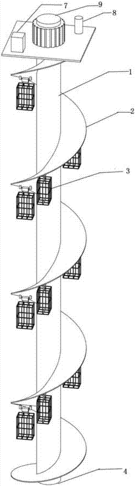
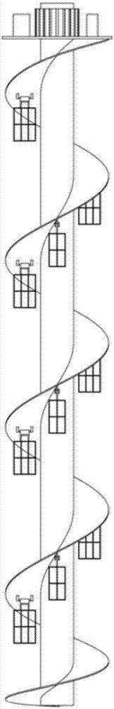
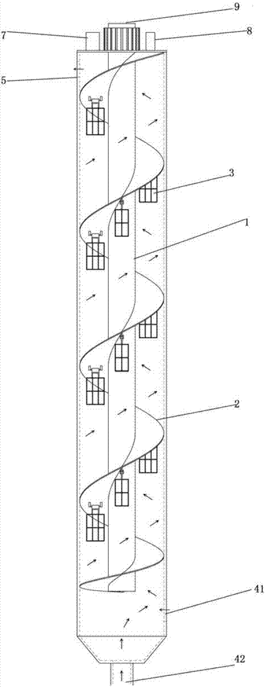
[0038] Such as Figure 1-7 Shown, a kind of vertical push-flow photocatalytic reactor of distribution flow inner diffusion on multi-tray, the lamp tube 9 that is attached with quartz sleeve 1 in the photocatalytic reactor lining, quartz sleeve 1 is coaxial with reactor, reaction From the bottom to the top of the reactor, there is a spirally rising tray 2 with the quartz sleeve 1 as the axis, and a plurality of catalyst trays 3 are suspended in the gap space between the upper and lower trays 2, and the water inlet 4 is located at the top of the photocatalytic reactor. In the lower part, the water outlet 5 is arranged on the upper part of the photocatalytic reactor. The catalyst tray 3 is net-shaped, evenly and spirally hung on the tray 2 in the pho...


PUM


Abstract

The invention relates to a multi-tower-plate stream distribution in-diffusion vertical plug-flow photocatalysis reactor. A modulator tube of a quartz socket tube is attached to the lining of the multi-tower-plate stream distribution in-diffusion vertical plug-flow photocatalysis reactor, the quartz socket tube is coaxial to the reactor, tower plates which are in a spiral rising shape and of which the axle is the quartz socket tube are arranged from the bottom to the top of the reactor, multiple catalyst trays are hung on the space between an upper tower plate and a lower tower plate, water inlets are formed at the lower portion of the photocatalysis reactor, and a water outlet is formed at the upper portion of the photocatalysis reactor. Through the coordination of the multiple spiral tower plates in the photocatalysis reactor and the catalyst trays which are hung between the multiple tower plates and are distributed in a spiral shape, the multiple spiral tower plates play an effect of guiding water streams, so that catalysts in the catalyst trays fully react with sewage, and thus the photocatalysis reaction efficiency is improved. The multi-tower-plate stream distribution in-diffusion vertical plug-flow photocatalysis reactor is simple and reasonable in structure, convenient to assemble and disassemble, is convenient to adjust and clean, low in operation maintenance cost, diversified in dirt removing variety, high in efficiency, stable in operation, simple in management, and is applied to treatment of various kinds of waster water.

Description

technical field [0001] The invention relates to sewage treatment equipment, in particular to a vertical push-flow photocatalytic reactor with flow distribution and internal diffusion on multiple trays. Background technique [0002] The photocatalytic reactor is the place where the photocatalytic reaction occurs, and the design of an efficient and easy-to-use reactor plays a very important role in the scientific research and practical application of the photocatalytic reaction. Since the 1980s, heterogeneous photocatalysis of nano-semiconductor materials has gained more and more attention in the field of environmental protection. The photocatalytic reaction can carry out a deep reaction at room temperature, completely mineralize and remove a variety of organic pollutants, especially in the removal of toxic and harmful substances that are difficult to biodegrade, and is considered to be a very promising Environmental pollution deep purification technology. As a place where p...

Claims


Application Information

Patent Timeline
Patent Type & Authority Applications(China)
IPC IPC(8): C02F1/32
CPCC02F1/32C02F2305/10
Inventor 王家强王伟李懿舟
Owner YUNNAN UNIV
Why Eureka
Try Eureka