Photoluminescent liquid crystal display

a liquid crystal display and photoluminescent technology, applied in the field of liquid crystal display, can solve the problems of reducing contrast ratio, reducing the life of liquid crystals that have absorbed ultraviolet light, and reducing light loss, so as to prevent the deterioration of liquid crystals, prolong the life, and improve the luminous efficiency

Inactive Publication Date: 2006-11-02
SAMSUNG ELECTRONICS CO LTD
View PDF17 Cites 76 Cited by
  • Summary
  • Abstract
  • Description
  • Claims
  • Application Information

AI Technical Summary

Benefits of technology

[0010] The present invention provides a photoluminescent liquid crystal display (PL-LCD) that has improved luminous efficiency and extended lifetime by preventing the deterioration of liquid crystals caused by UV light exciting phosphors.

Problems solved by technology

These color filters transmit only light of certain wavelengths, thereby causing great light loss.
Therefore, the UV rays in the ambient light can excite phosphor regardless of whether the excitation of the phosphor is required to display an image on the LCD, thus lowering contrast ratio.
In addition, the liquid crystals that have absorbed UV light deteriorate and have a reduced lifetime.
Furthermore, since the PL-LCD is not a color-filter-free structure, light loss caused by the color filters still occurs.

Method used


Image

  • Photoluminescent liquid crystal display
  • Photoluminescent liquid crystal display
  • Photoluminescent liquid crystal display

Examples


Embodiment Construction

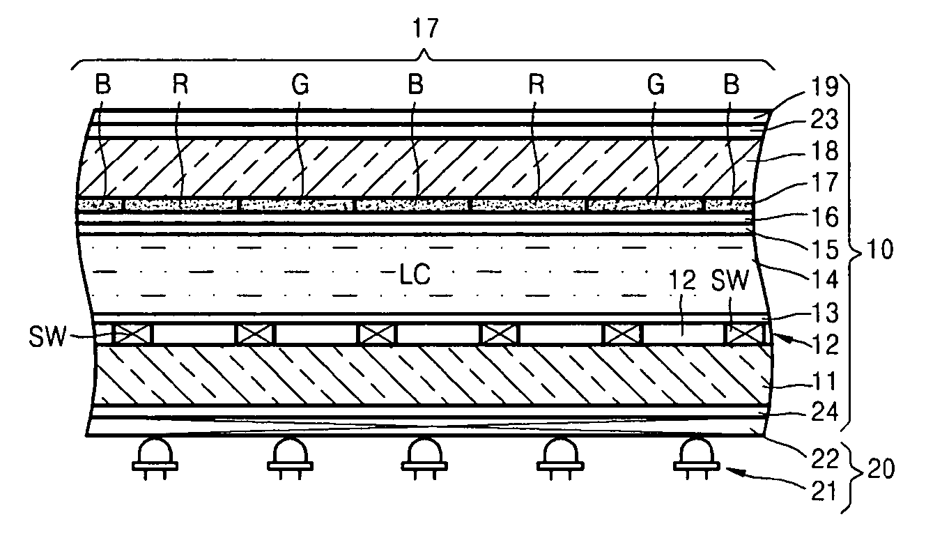
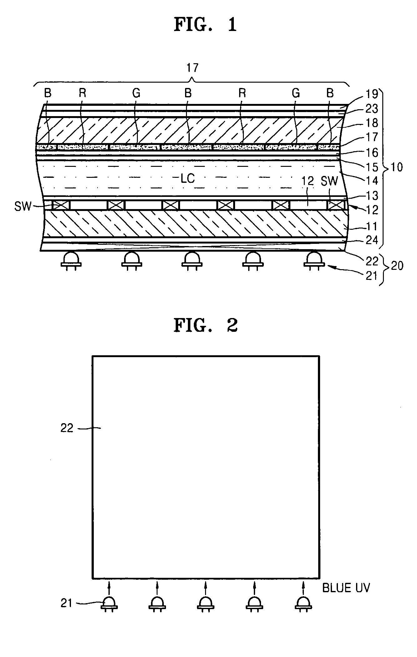
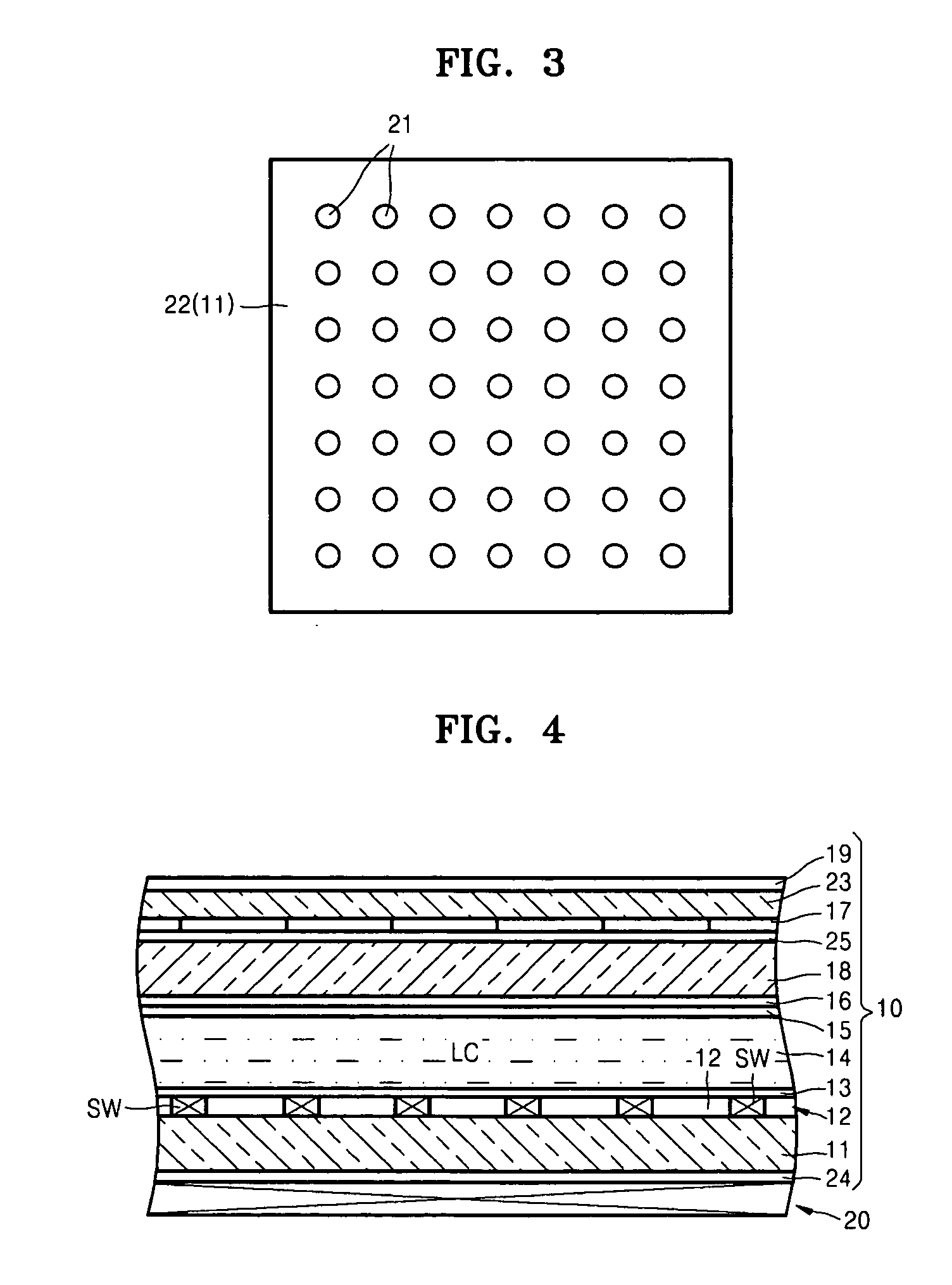
[0022] Hereinafter, the present invention will be described more fully with reference to the accompanying drawings, in which exemplary embodiments of the invention are shown. This invention may, however, be embodied in many different forms and should not be construed as limited to the exemplary embodiments set forth herein. Rather, these embodiments are provided so that this disclosure will be thorough and complete, and will fully convey the scope of the invention to those skilled in the art. In the drawings, lengths and sizes of layers and regions may be exaggerated for clarity.

[0023] It will be understood that when an element or layer is referred to as being “on” another element or layer, the element or layer can be directly on another element or layer or intervening elements or layers. In contrast, when an element is referred to as being “directly on” another element or layer, there are no intervening elements or layers present. Like numbers refer to like elements throughout. As...


PUM


Abstract

A photoluminescent liquid crystal display (PL-LCD) includes: a front plate and a rear plate; liquid crystals disposed between the front and rear plates; an electrode that is disposed on an inner surface of each of the front and rear plates and forms an electric field in the liquid crystals; an emitting layer that is formed on the front plate and emits visible light by being excited by light having a wavelength of about 390 nm to about 410 nm; a light source unit that is formed on a rear side of the rear plate and includes a lamp emitting near blue-UV light having a wavelength of about 390 nm to about 410 nm toward the emitting layer; and a UV filter blocking UV rays in ambient light from entering a front side of the front plate.

Description

[0001] This application claims priority to Korean Patent Application Nos. 10-2005-0034918, filed on Apr. 27, 2005, and 10-2005-0037069, filed on May 3, 2005, and all the benefits accruing therefrom under 35 U.S.C. §119, and the contents of which in their entirety are herein incorporated by reference. BACKGROUND OF THE INVENTION [0002] 1. Field of the Invention [0003] The present invention relates to a liquid crystal display, and more particularly, to a photoluminescent liquid crystal display (“PL-LCD”) with high luminous efficiency. [0004] 2. Description of the Related Art [0005] A liquid crystal display (“LCD”) is a non-active emissive display that requires an additional backlight device to display an image, and red (R), green (G) and blue (B) color filters for each pixel of the LCD to display a colored image. [0006] The R, G and B color filters respectively emit R, G and B light in white light incident from the backlight device. These color filters transmit only light of certain w...

Claims


Application Information

Patent Timeline
Patent Type & Authority Applications(United States)
IPC IPC(8): H01J1/62
CPCG02F2201/086G02F1/133617
Inventor IM, SEOUNG-JAEKIM, BYUNG-KICHOI, JAE-YOUNGHWANG, IN-SUNPARK, HAE-IL
Owner SAMSUNG ELECTRONICS CO LTD
Why Eureka
Try Eureka