Backlight unit and liquid crystal display device

a liquid crystal display and backlight technology, applied in lighting support devices, lighting and heating apparatuses, instruments, etc., can solve the problems of non-uniformity cyclically occurring in luminance and chromaticity, difficult to uniformly illuminate the entire surface of the liquid crystal display panel, and gradual difficulty in uniformly mixing led lights in the case, etc., to achieve satisfactory suppression of color non-uniformity, improve luminance uniformity, and make the distance between each adjacent light source remarkably long

Inactive Publication Date: 2006-11-02
SONY CORP
View PDF11 Cites 15 Cited by
  • Summary
  • Abstract
  • Description
  • Claims
  • Application Information

AI Technical Summary

Benefits of technology

[0012] As mentioned above, in the backlight unit and the liquid crystal display device according to the embodiments of the present invention, the light sources are arranged so that each of the light sources are spaced apart from the adjacent other ones of the light sources in two or more arrangement directions in the plane where the light sources are arranged; that is to say, a desired number of light sources are arranged in a predetermined space in the backlight unit so that each of the light sources is spaced as apart as possible from the adjacent ones in a plurality of directions. Generally, as mentioned above, light sources such as light emitting diodes are arranged comparatively densely in one direction and comparatively sparsely in another direction. On the other hand, in the embodiments of the present invention, light sources are spaced apart from one another in two or more directions so that the light sources are arranged at least equal intervals in a plurality of arrangement directions. In addition, the light sources are arranged so that the longest distance between each of the light sources and the adjacent other ones of the light sources in two or more directions is set to a ratio between 1 and 2 with respect to the shortest distance therebetween. Accordingly, as compared with the related art, the distance between each adjacent ones of the light sources can be made remarkably long, so that luminance uniformity can be improved.
[0013] In addition, in the embodiments of the present invention, the light sources include light sources for emitting two

Problems solved by technology

However, it is difficult to uniformly illuminate the entire surface of the liquid crystal display panel, and there is a case where an image of a light source itself becomes visible.
In addition, it is desired that liquid crystal display devices and backlight units be made increasingly smaller in size and thickness, so that it is becoming gradually difficult to uniformly mix lights from LEDs in the case where the LEDs are used as light sources.
As a res

Method used


Image

  • Backlight unit and liquid crystal display device
  • Backlight unit and liquid crystal display device
  • Backlight unit and liquid crystal display device

Examples


first embodiment

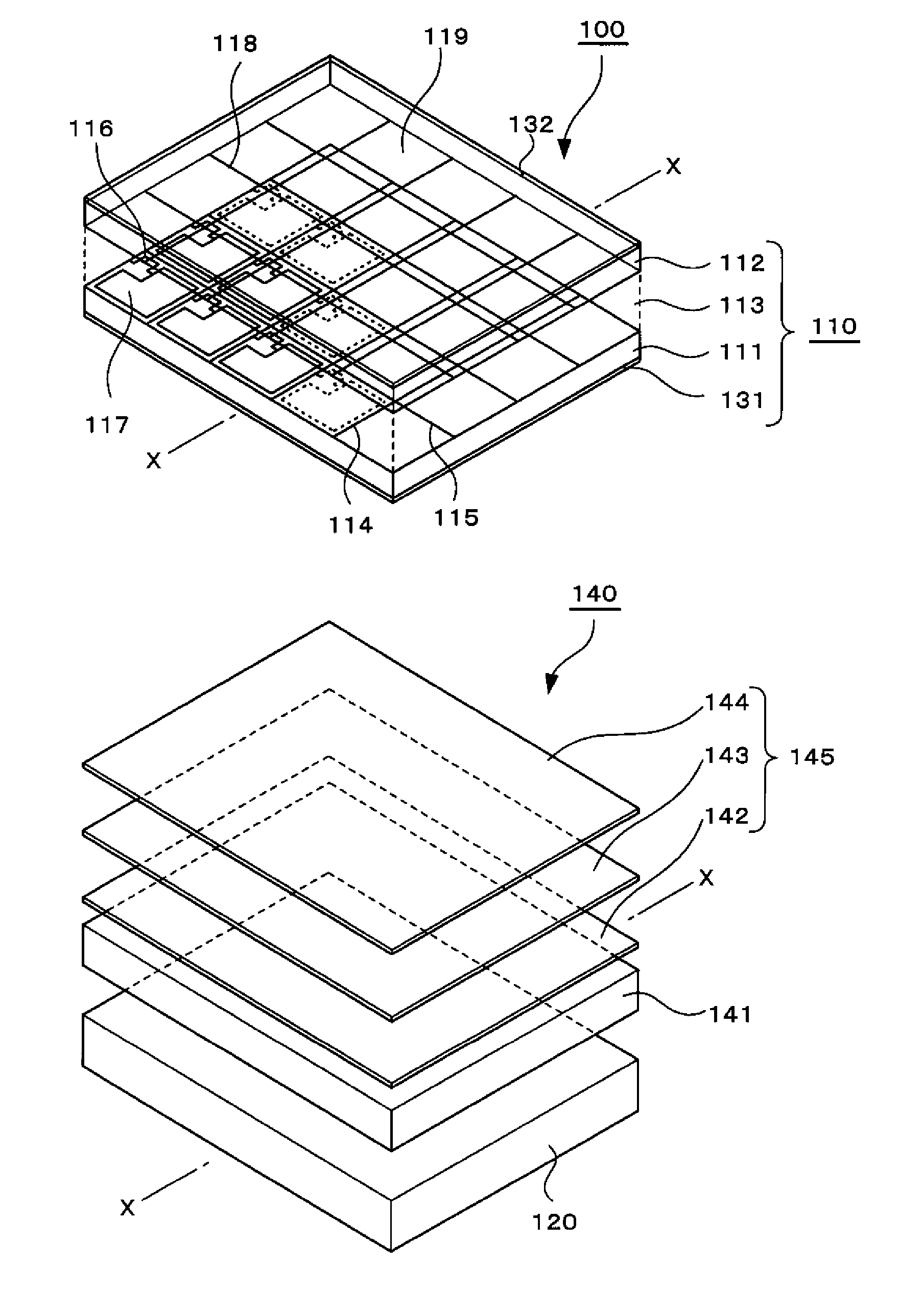
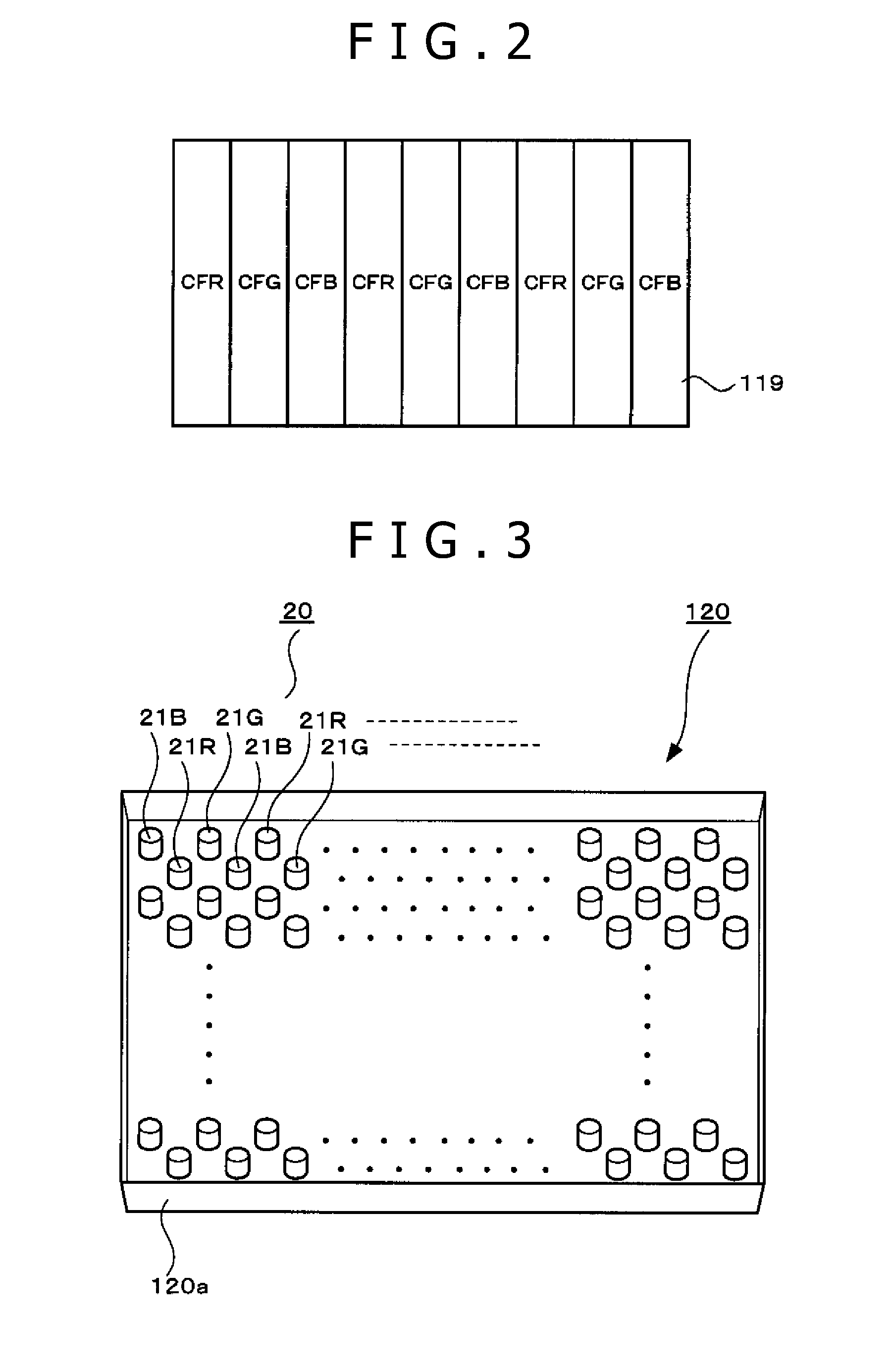
[0052]FIG. 6 is a schematic plan view of the construction of a main section of the backlight unit according to a first embodiment of the present invention. In this embodiment, the light sources 20 are arranged in a triangular pattern, i.e., at approximately equal intervals in three directions, one of which is an arrangement direction extending laterally as shown by dashed lines a1, a2, . . . , in FIG. 6, another of which is an arrangement direction extending obliquely at an angle of approximately 60 degrees relative to the lateral arrangement direction as shown by dashed lines b1, b2, . . . , in FIG. 6, and the other of which is an arrangement direction extending obliquely at an angle of approximately 120 degrees relative to the lateral arrangement direction as shown by dashed lines c1, c2, . . . , in FIG. 6. FIG. 6 shows a case where light sources for emitting light of one kind of color A, for example, white light emitting diodes or light emitting diodes for another color, are used...

second embodiment

[0053]FIG. 7 is a schematic plan view of the construction of a main section of the backlight unit according to a second embodiment of the present invention. In this embodiment, the light sources 20 are arranged in a square grid-like pattern, i.e., at approximately equal intervals in two directions, one of which is an arrangement direction extending laterally as shown by dashed lines a1, a2, . . . , in FIG. 7, and the other of which is an arrangement direction approximately orthogonal to the lateral arrangement direction as shown by dashed lines d1, d2, . . . , in FIG. 7. FIG. 7 shows a case where light sources for emitting two kinds of color lights A and B, for example, light emitting diodes for two colors selected from among red, green, blue and white, are used as the light sources 20. The ratio of the used numbers of the light sources 20 for the two colors is 1:1, and the light sources 20 for the colors A and B are arranged so that each of the light sources 20 for either one of th...

third embodiment

[0054]FIG. 8 is a schematic plan view of the construction of a main section of the backlight unit according to a third embodiment of the present invention. In this embodiment, the light sources 20 are arranged in a triangular pattern, and in FIG. 8, identical reference numerals are used to denote sections corresponding to those shown in FIG. 6 and the description of the same sections is omitted. FIG. 8 shows a case where light sources for emitting two kinds of color lights A and B are used as the light sources 20 and the used numbers of the light sources 20 for the respective colors A and B are set to a ratio of 2:1. In addition, in the case where light sources for two or more kinds of color lights are used, the optimum ratio of the used numbers of the light sources is not necessarily 1:1 and is influenced by visibility to each of the colors. Depending on the kind or number of colors, the optimum ratio need not be limited to 2:1 and may also become 3:2, 4:3 or the like. In this embo...


PUM


Abstract

A backlight unit having light sources being arranged to be spaced apart from adjacent other light sources in two or more arrangement directions in a plane where the light sources are arranged.

Description

BACKGROUND OF THE INVENTION [0001] 1. Field of the Invention [0002] The present invention relates to a backlight unit for illuminating a liquid crystal display panel from the back thereof, and to a liquid crystal display device using the backlight unit. [0003] 2. Description of Related Art [0004] In recent years, instead of CRTs (Cathode Ray Tubes), extremely thin-sized display devices such as liquid crystal display devices (LCDs) and plasma display panels (PDPs) have been proposed and put to practical use as display devices for television sets. Technical research and development are being particularly promoted on liquid crystal display devices using liquid crystal display panels, because the liquid crystal display devices can be driven with low power consumption and are becoming widespread with reductions in price of large-sized liquid crystal display panels. [0005] The majority of such liquid crystal display devices adopt a backlight system which displays a color image by illumina...

Claims


Application Information

Patent Timeline
IPC IPC(8): F21V5/00F21V9/00
CPCG02F1/133603G02F1/133609G02F2001/133613G02F2001/133317G02F1/133611G02F1/133317G02F1/133613
Inventor MIZUTA, MINORU
Owner SONY CORP
Why Eureka
Try Eureka