
Time synchronization, deterministic data delivery and redundancy for cascaded nodes on full duplex ethernet networks

Active Publication Date: 2006-11-02
ROCKWELL AUTOMATION TECH
View PDF18 Cites 153 Cited by
  • Summary
  • Abstract
  • Description
  • Claims
  • Application Information

AI Technical Summary

Benefits of technology

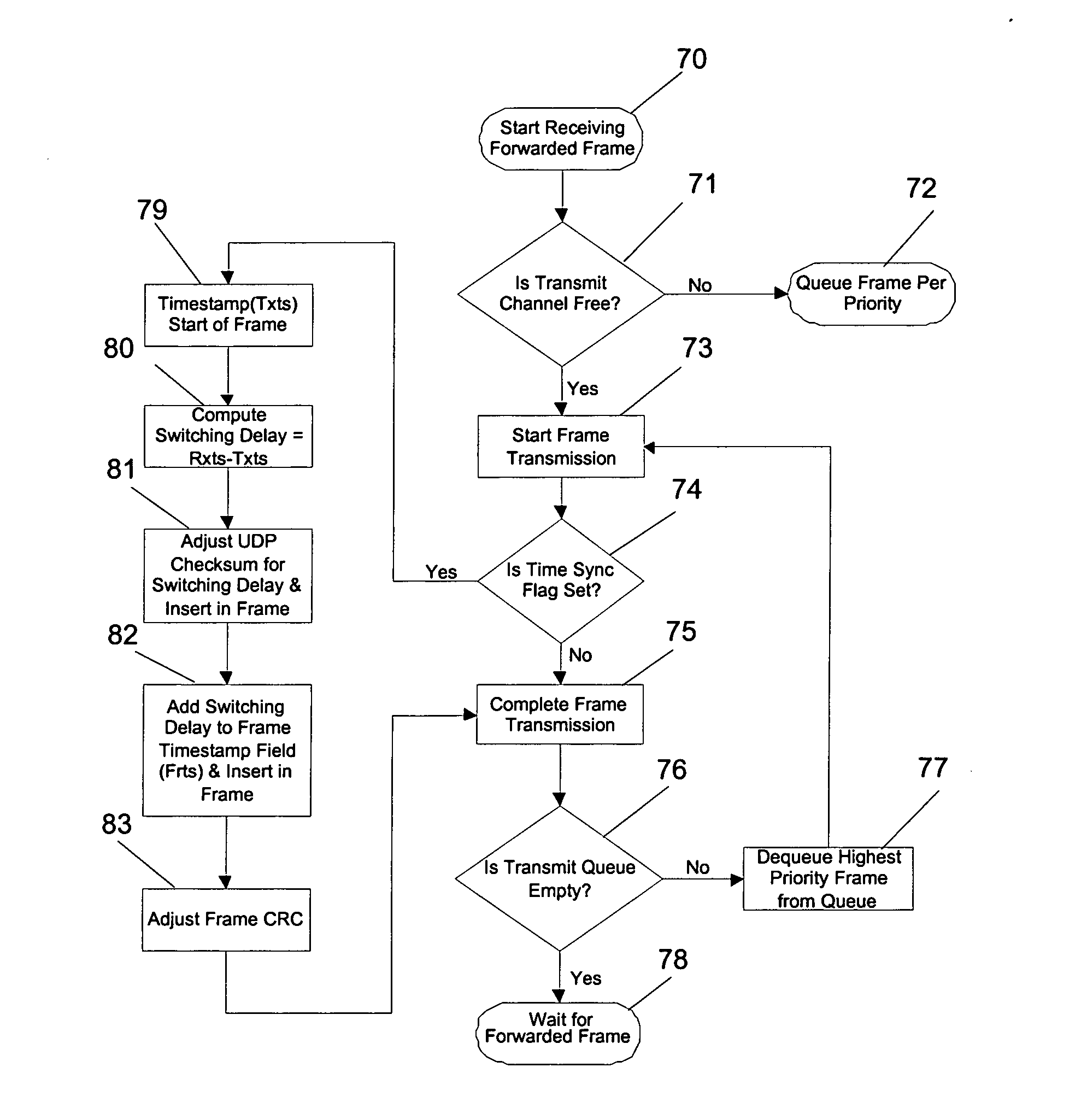
[0011] To achieve precision time synchronization, the node switch will accurately account for delays through the switch. The delays will be added on the fly to synchronization packets and the UDP checksum and frame CRC will be adjusted. This approach will result in significant improvement over systems using boundary clocks.

Problems solved by technology

This bus topology can be accomplished through half duplex Ethernet, but this type of network has several drawbacks such as collisions, a 100-meter copper cable length limit and technology obsolescence.
Further, data throughput is limited to 100 Mbps by the half duplex nature of network.
These limitations make it undesirable to use half duplex Ethernet for distributed motion control applications.
This results in a delay corresponding to frame size plus intrinsic queuing and switching delay.
However, significant problems result for time synchronization and deterministic data delivery in a network with this topology.
There are random time delays introduced by the switches that affect time synchronization resulting in loss of synchronization precision and stability.
Even with use of boundary clocks on switches, it is difficult to achieve sub-microsecond level precision synchronization required for distributed motion control, when more than four switches are cascaded.
With store and forward architecture, significant random cumulative delays are introduced in the data delivery path resulting in non-deterministic data delivery and other performance issues.

Method used


Image

  • Time synchronization, deterministic data delivery and redundancy for cascaded nodes on full duplex ethernet networks
  • Time synchronization, deterministic data delivery and redundancy for cascaded nodes on full duplex ethernet networks
  • Time synchronization, deterministic data delivery and redundancy for cascaded nodes on full duplex ethernet networks

Examples


Embodiment Construction

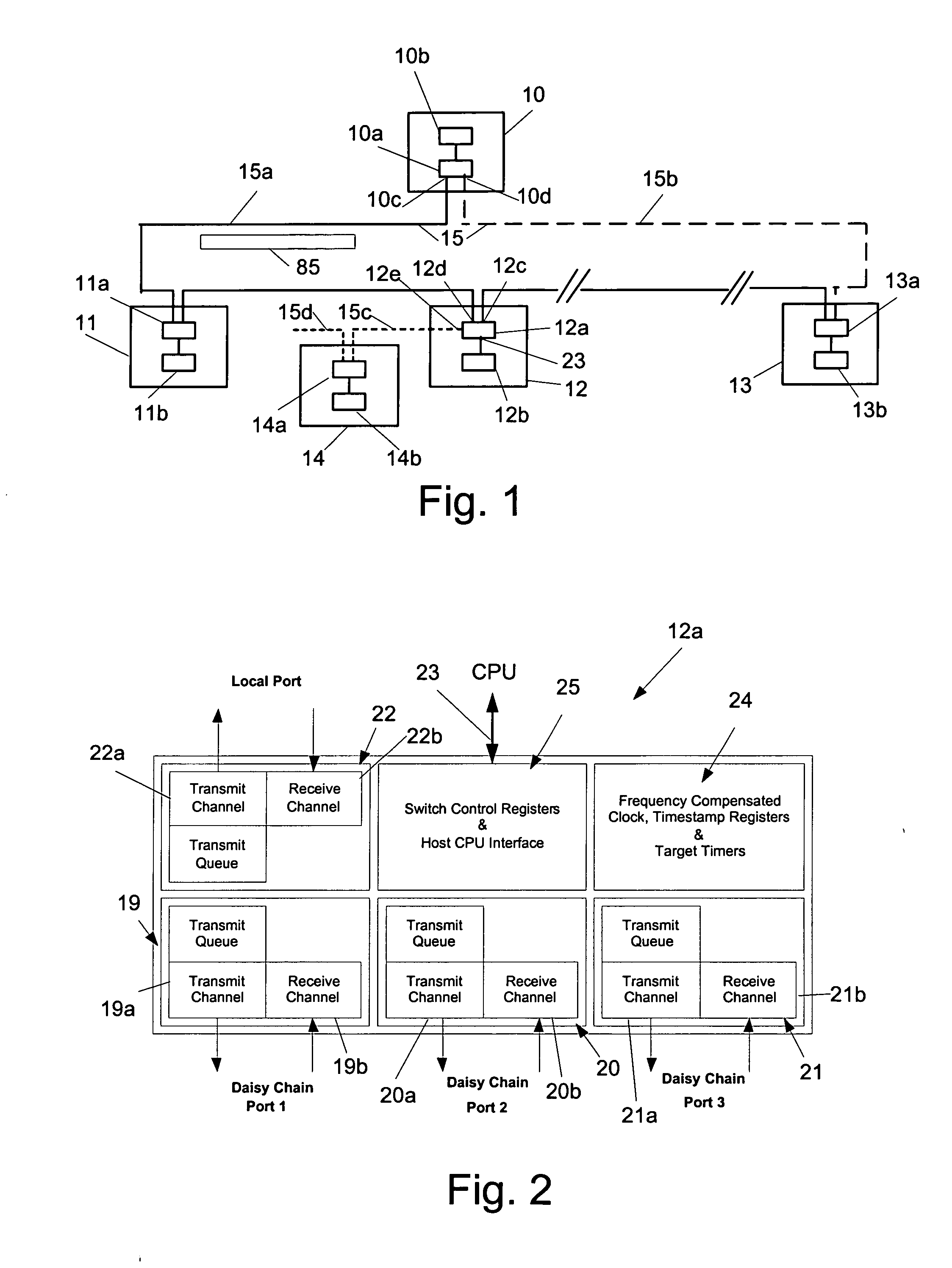
[0024] Referring now to FIG. 1, nodes 10, 11, 12 and 13 are connected through a communication network 15. In this embodiment the network 15 is a full duplex Ethernet network operating at data rates up to 200 Mbps. Nodes 10, 11, 12 and 13 may be, for example, industrial controllers, network bridges, remote I / O modules, standard motor drives, servo motor drives, or human-machine interfaces. If any of these nodes are controllers, then these controllers may be connected to local I / O modules and devices, including motion control devices for controlling motors, robots and other motion devices. To provide redundant network connections, the network 15 can take the form of a ring with two data paths 15a and 15b communicating with two respective ports 10c and 10d on a designated supervisory node device 10. The designated supervisory node device 10 may be a special controller, a special network bridge or any other special device designed for this role. This device has one master clock from whi...


PUM


Abstract

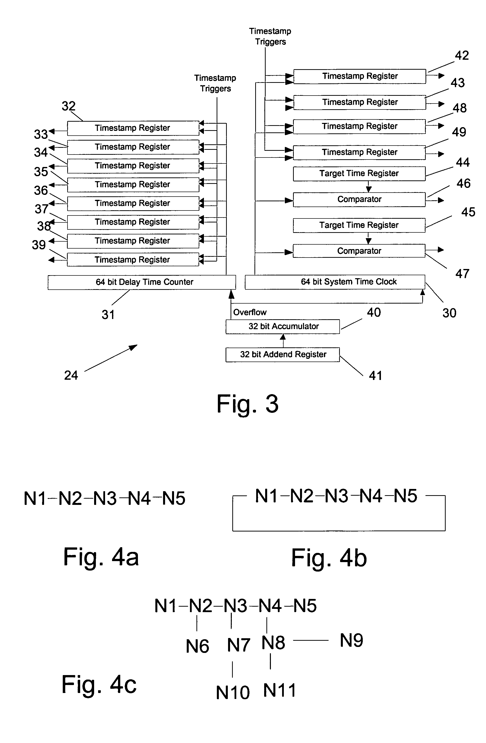
A method and circuit for precisely synchronizing clocks in separate nodes on a communication network is provided by adjusting timestamps and related data in network messages. The circuit will allow a daisy-chain connection of the nodes and will forward time synchronization frames while accounting for delays in a manner that does not use boundary clocks, but does not depart from the IEEE 1588 standard protocol. The delays will be added on the fly to synchronization packets and the IP checksum and frame CRC will be adjusted. Deterministic data delivery and redundant data paths are also provided in a full duplex Ethernet network.

Description

CROSS-REFERENCE TO RELATED APPLICATIONS [0001] Not Applicable STATEMENT REGARDING FEDERALLY SPONSORED RESEARCH OR DEVELOPMENT [0002] Not ApplicableTECHNICAL FIELD [0003] The present invention relates generally to industrial control devices for the control of machines and processes and in particular, industrial control devices which can be connected to a distributed high speed network. BACKGROUND ART [0004] In industrial control, there is a class of distributed motion control applications that require both precision time synchronization and deterministic data delivery. Precision time synchronization at the nodes can be achieved with a network communication protocol according to IEEE 1588, Standard for a Precision Clock Synchronization Protocol for Networked Measurement and Control Systems, 2002, and by using frequency-compensated clocks as disclosed in our prior U.S. patent application Ser. No. 10 / 347,658 filed Jul. 22, 2003. Motion control applications also require deterministic dat...

Claims


Application Information

Patent Timeline
IPC IPC(8): H04J3/06H04L7/00
CPCH04J3/0664H04L12/4625H04J3/0673
Inventor BALASUBRAMANIAN, SIVARAMMOLDOVANSKY, ANATOLYHARRIS, KENDAL R.
Owner ROCKWELL AUTOMATION TECH
Learn More