Digital frequency synthesizer

a digital frequency and frequency divider technology, applied in the field of digital frequency synthesis, can solve the problems of jitter and cumulative inaccuracy that limit the applications of such a frequency divider, and achieve the effect of greater output frequency accuracy

Active Publication Date: 2006-11-02
ANALOG DEVICES INC
View PDF24 Cites 7 Cited by
  • Summary
  • Abstract
  • Description
  • Claims
  • Application Information

AI Technical Summary

Benefits of technology

[0012] An advantage of the present invention is that there is no accumulation of error in the synthesized output frequency leading to greater accuracy in the output frequency, which makes the invention useful for a greater variety of applications.
[0013] Another advantage of the present invention is that jitter can be held to a minimum by using a large number of phase signals.
[0014] Yet another advantage is that the amount of circuitry needed to implement the present invention does not increase by a lar...

Problems solved by technology

Both the jitter and cumulative inaccuracy li...

Method used


Image

  • Digital frequency synthesizer
  • Digital frequency synthesizer
  • Digital frequency synthesizer

Examples


embodiment 140

[0062]FIG. 2D shows a general embodiment 140 of the encoding decoding circuitry for use in the phase selection circuitry of the present invention. There is an initial stage for computing the parameter e, and then log2 p subsequent stages in the encoding block 142. The decoder decodes the log2 p binary signals, one from each of the stages.

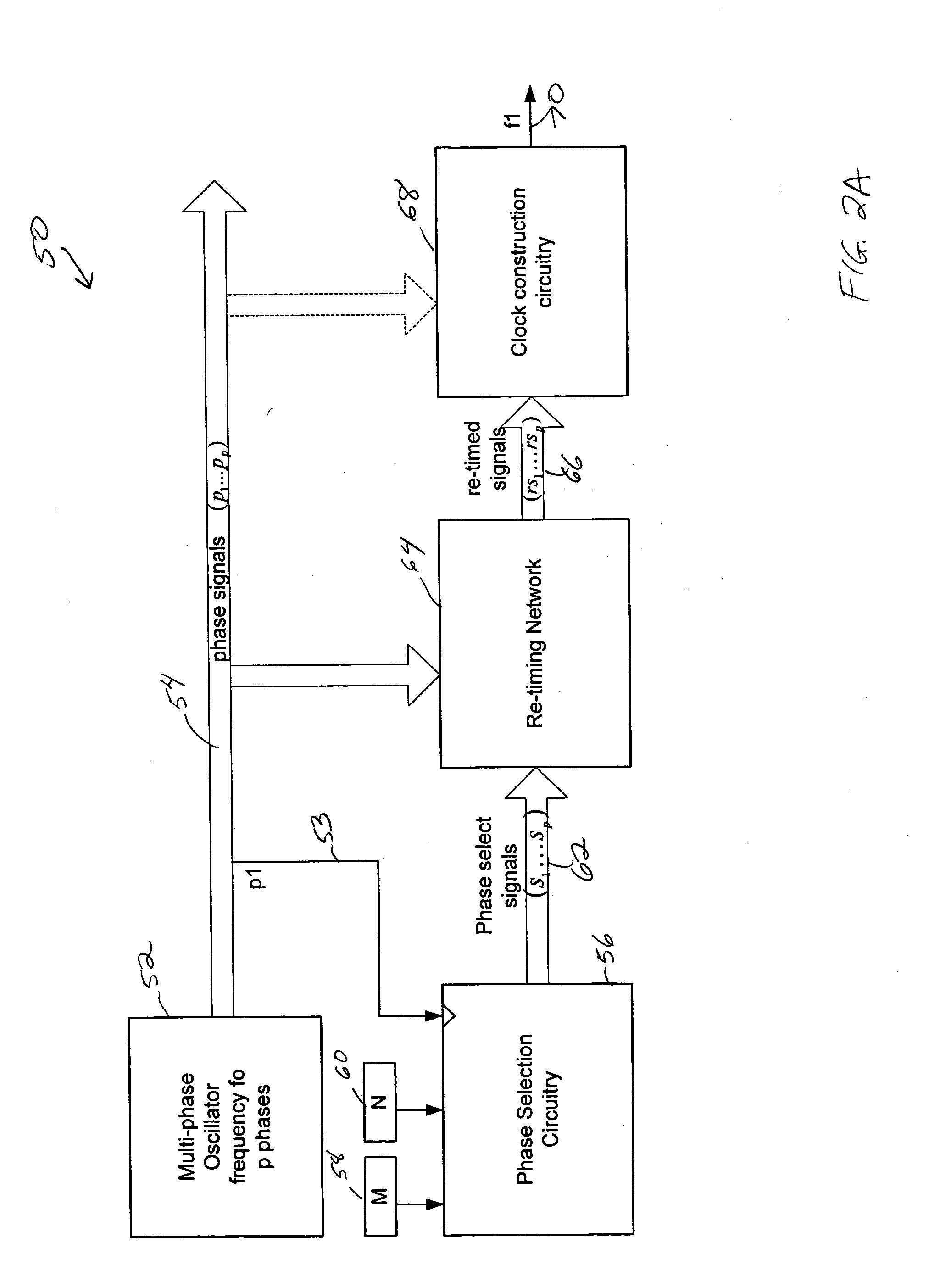
[0063]FIG. 4 shows an embodiment of the retiming network 64 of the present invention. The phase select signals 62 leaving the arithmetic unit are synchronous with the clock used for that unit, specifically one of the phases of the multi-phase clock (phase 153 is shown in FIG. 2A). In order to synthesize to the desired frequency, with the phase accuracy available from the multi-phase clock, these signals must be made synchronous with the phase signals they select, if active. The network 64 thus includes circuitry that receives each of the phase select signals 62 and re-clocks the signals to have the actual phase that the name of the phase select sign...

first embodiment

[0067] In FIG. 6B, the re-timed signals taken from the last rank of the retiming network 64 are simply OR'ed together in gate 244. This is not as accurate as the first embodiment, as there is a flip-flop delay between the actual phase signal of the multi-phase oscillator and the output, but may be acceptable in some circumstances.

[0068]FIG. 7 shows one of many applications 260 of the frequency synthesizer of the present invention. A multiphase clock such as a rotary traveling wave oscillator 262 is setup to provide and distribute multiple phases to a plurality of blocks 264, 266, 268, 270 on an integrated circuit. Each of the blocks, a PCI block 264, a Graphics Interface block 266, a Co-processor block 268, and a memory bus block 270, has a need for a different frequency of operation which may be optimal for the functions the block carries out. A PCI block 264 for example, may need to operate at 2.5 GHz, the Graphics Interface block 266 may need to operate at 8 GHz, the Co-processor...


PUM


Abstract

A system and method for synthesizing a frequency using a multi-phase oscillator. A state machine operating on one of the phases of the oscillator computes, based on a pair of input integers, a phase select vector that indicates when a particular phase of the multi-phase oscillator should be selected when a transition of the waveform of the output frequency is needed. The phase select vector is then re-timed to form a retimed phase vector so that each phase select signal is in phase with signal it is designed to select. The signals in the retimed phase vector then can be combined to create the output frequency directly or can be used to select the corresponding phase of the multi-phase oscillator, if more accuracy is desired. In one embodiment, the multi-phase oscillator is a rotary traveling wave oscillator which provides highly accurate multiple phases.

Description

CROSS-REFERENCE TO RELATED APPLICATIONS [0001] This application incorporates by reference U.S. Pat. No. 6,556,089, issued on Apr. 29, 2003, titled “Electronic Circuitry”. FIELD OF THE INVENTION [0002] The present invention relates generally to digital frequency synthesis and more particularly to synthesized frequencies that have high accuracy and low jitter. DESCRIPTION OF THE RELATED ART [0003] It is desirable to create a frequency synthesis circuit having integer inputs M, N, with M / N<1, so that a lower frequency clock can be synthesized from a rotary clock, usually running at a high frequency. Conventional synthesizers, shown in FIGS. 1A and 1B have problems with both jitter and cumulative inaccuracy. [0004] Jitter results from having only a limited number of phases, as shown in FIG. 1A and 1B, such that if the synthesized frequency requires a phase that is not present, phases on either side of the missing phase must be used. For example, if it is desired to synthesize T1=4.25...

Claims


Application Information

Patent Timeline
IPC IPC(8): H03D3/24
CPCH03L7/16
Inventor ZIESLER, CONRAD HAVLUJ
Owner ANALOG DEVICES INC
Why Eureka
Try Eureka