Electric fluid pump

Inactive Publication Date: 2006-11-02
TESMA INT INC
View PDF12 Cites 34 Cited by
  • Summary
  • Abstract
  • Description
  • Claims
  • Application Information

AI Technical Summary

Benefits of technology

[0018] In an alternate embodiment, the rotor and impeller form a unitary body, in order to reduce the number of parts.
[0019] All embodiments eliminate the need for the conventional aluminum plate, resulting in the minimization of drag created

Problems solved by technology

These belts and pulleys are cumbersome, bulky, noisy, and transfer power (torque) inefficiently.
Another disadvantage is that these pumps have their output dictated by the rotational speed of the engine.
This leads to poor efficiencies and increased power losses due to the requirement for a bypass.
However, while aluminum has excellent heat transfer characteristics, it also decreases mot

Method used


Image

  • Electric fluid pump
  • Electric fluid pump
  • Electric fluid pump

Examples


Example

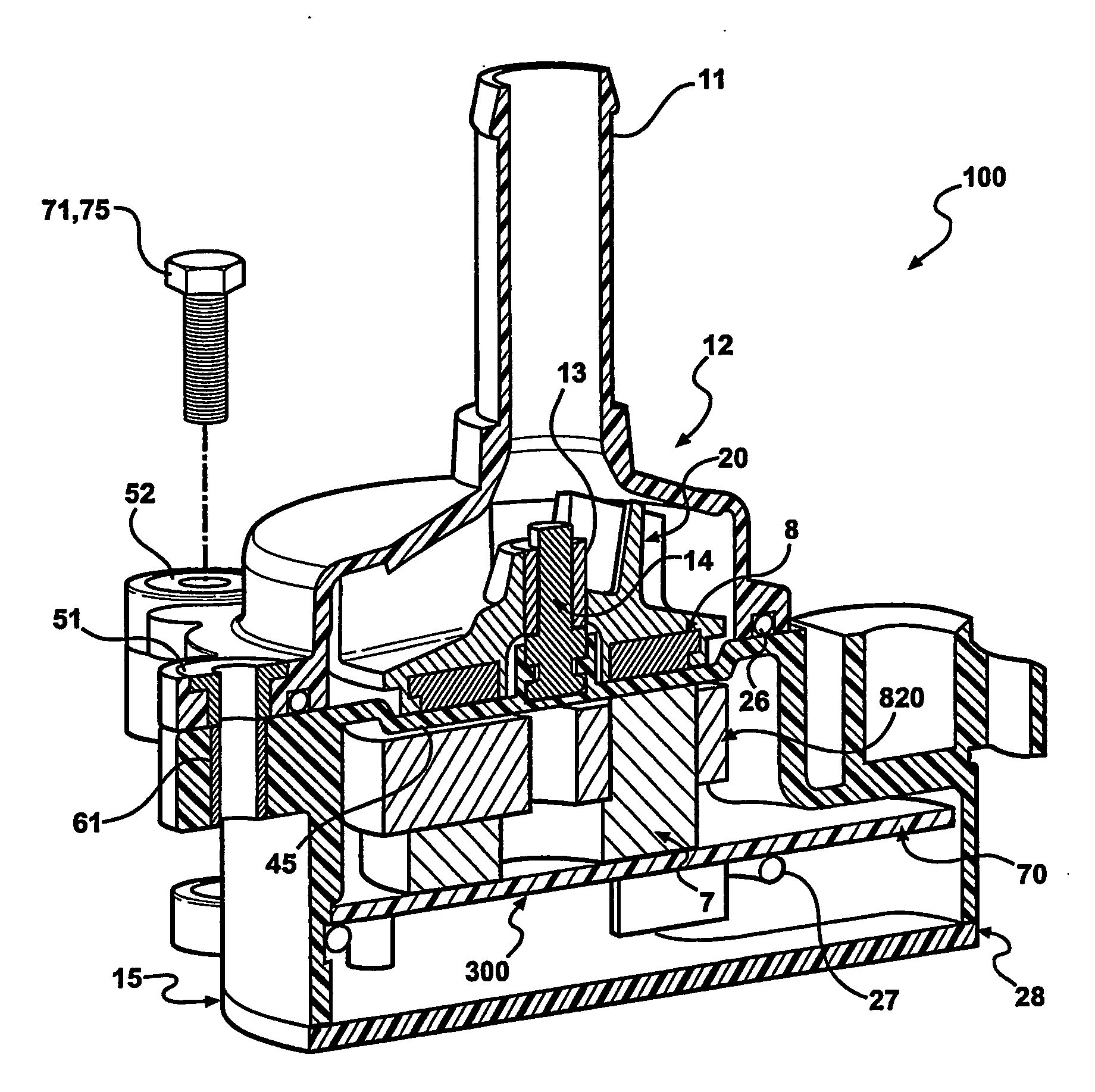
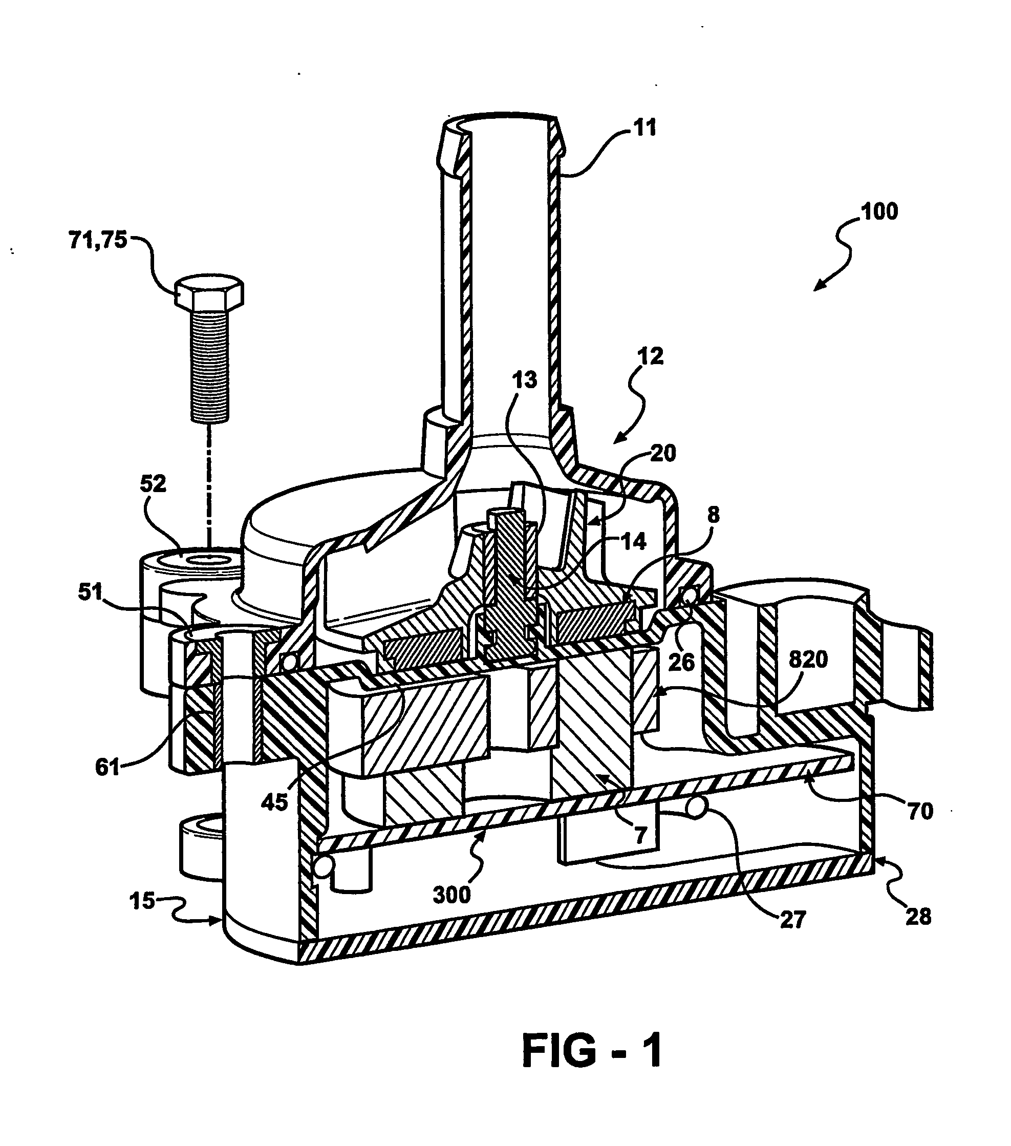
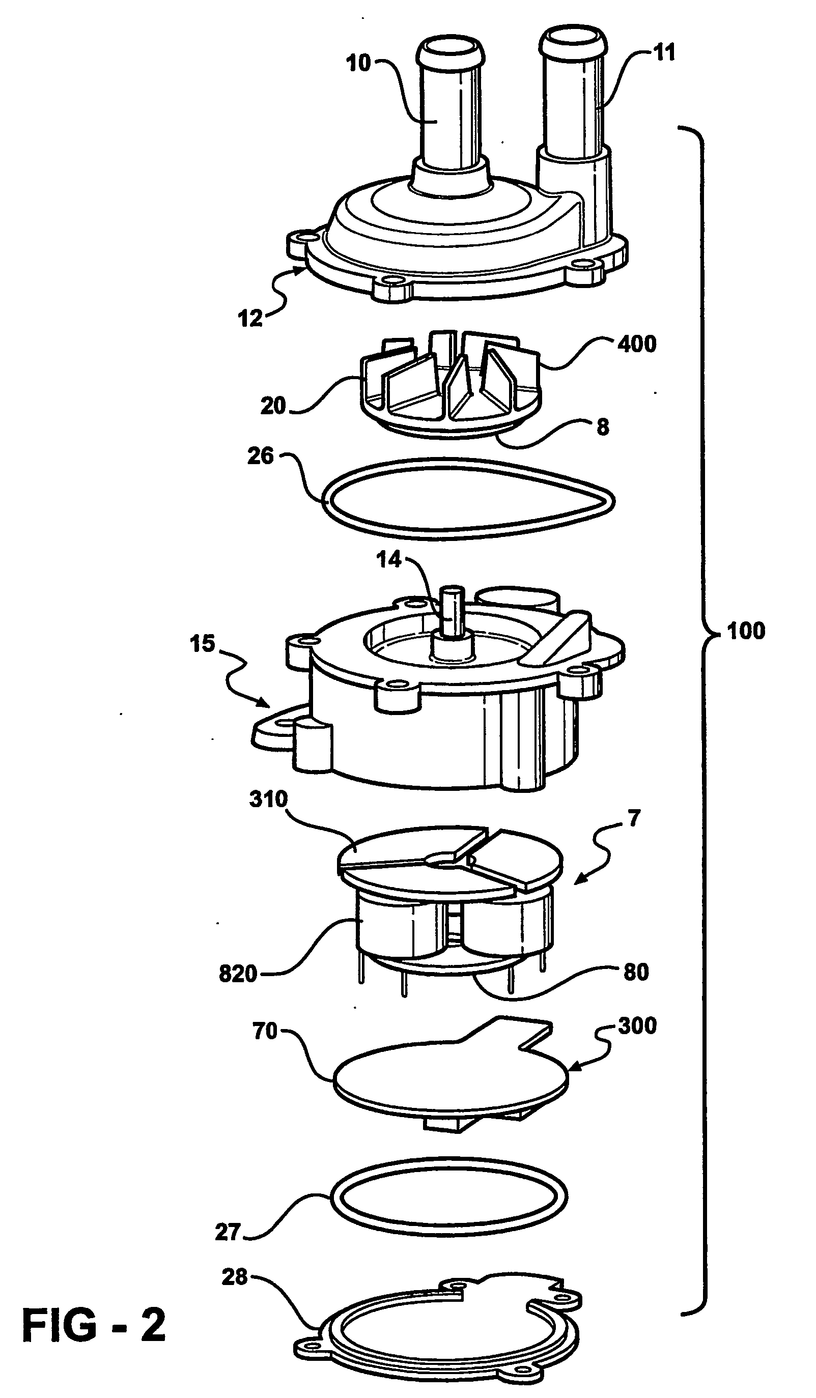
[0040] Referring to FIGS. 1-8, a pump assembly 100 is shown including an upper housing 12 with a fluid inlet 10 and outlet 11 and a lower housing 15. The upper 12 and lower 15 housing are preferably molded of polymeric material to provide good thermal characteristics and allow heat to dissipate into fluid within the housing. An impeller 20, preferably formed from injection-molded plastic, is seated within the interior volume of the upper housing 12. The impeller 20 is integrally formed with a permanent magnet and “back iron” assembly 8, which also serves as the rotor of a DC motor, to be described shortly. In one embodiment, the plastic impeller 20 encapsulates the magnet and “back iron” assembly 8 due to an overmolding or insert molding operation. Both the impeller 20 and rotor 8 include a central opening to accommodate both a bushing 13 and low friction shaft or spindle 14. The impeller 20 rotates around the shaft 14 that is fixed to the lower housing 15. The impeller / magnet assem...


PUM


Abstract

An electric fluid pump includes an upper housing having a fluid inlet and outlet. An impeller is seated within the upper housing for pumping fluid between the inlet and the outlet. The impeller includes at least one magnet secured thereto. A lower housing mates with the upper housing. The lower housing has an upper wall for closing the upper housing and a shaft extending from the upper wall for rotatably supporting the impeller. A stator is seated within the lower housing and spaced from the impeller by the upper wall. The stator includes a plurality of pillars supporting a winding of coils for producing a magnetic field to energize the magnet and rotate the impeller, and a plurality of top plates covering each of the coils and spaced apart by a predetermined gap for maintaining the magnetic field between the stator and the impeller. An end cap closes the stator within the lower housing.

Description

FIELD OF THE INVENTION [0001] The invention relates to a pump driven by a brushless direct current (DC) motor. More particularly, the invention relates to any fluid pump system using DC brushless motor technology to drive coolant (for water pumps) or oil (for engine and transmission pumps). BACKGROUND OF THE INVENTION [0002] The most common pump accessory arrangement found in automobiles utilizes the engine rotation to drive a shaft via a belt connection between a driving pulley (connected to the crankshaft) and a driven pulley. These belts and pulleys are cumbersome, bulky, noisy, and transfer power (torque) inefficiently. Another disadvantage is that these pumps have their output dictated by the rotational speed of the engine. Certain accessories that are coupled to the engine, such as the coolant and oil pumps, must be over-sized, because the pump output must deliver a minimum flow amount of fluid at low engine speeds. At higher engine speeds, such as those experienced under norm...

Claims


Application Information

Patent Timeline
IPC IPC(8): F04B17/00F04D13/06H02K5/128H02K7/14
CPCF04D13/0666F04D13/064H02K7/14H02K5/1282
Inventor LACROIX, MICHAEL C.BAJLON, DEANCLOUGH, MALCOLM J.
Owner TESMA INT INC
Why Eureka
Try Eureka