Wireless transmitter and amplifier

a technology of wireless transmitter and amplifier, applied in the direction of gated amplifier, electromagnetic wave modulation, baseband system details, etc., can solve the problems of power amplifiers operating inefficiently when mimo transmission is executed, degrading distortion characteristics, and affecting the efficiency of mimo transmission

Active Publication Date: 2006-11-02
KK TOSHIBA
View PDF5 Cites 51 Cited by
  • Summary
  • Abstract
  • Description
  • Claims
  • Application Information

AI Technical Summary

Benefits of technology

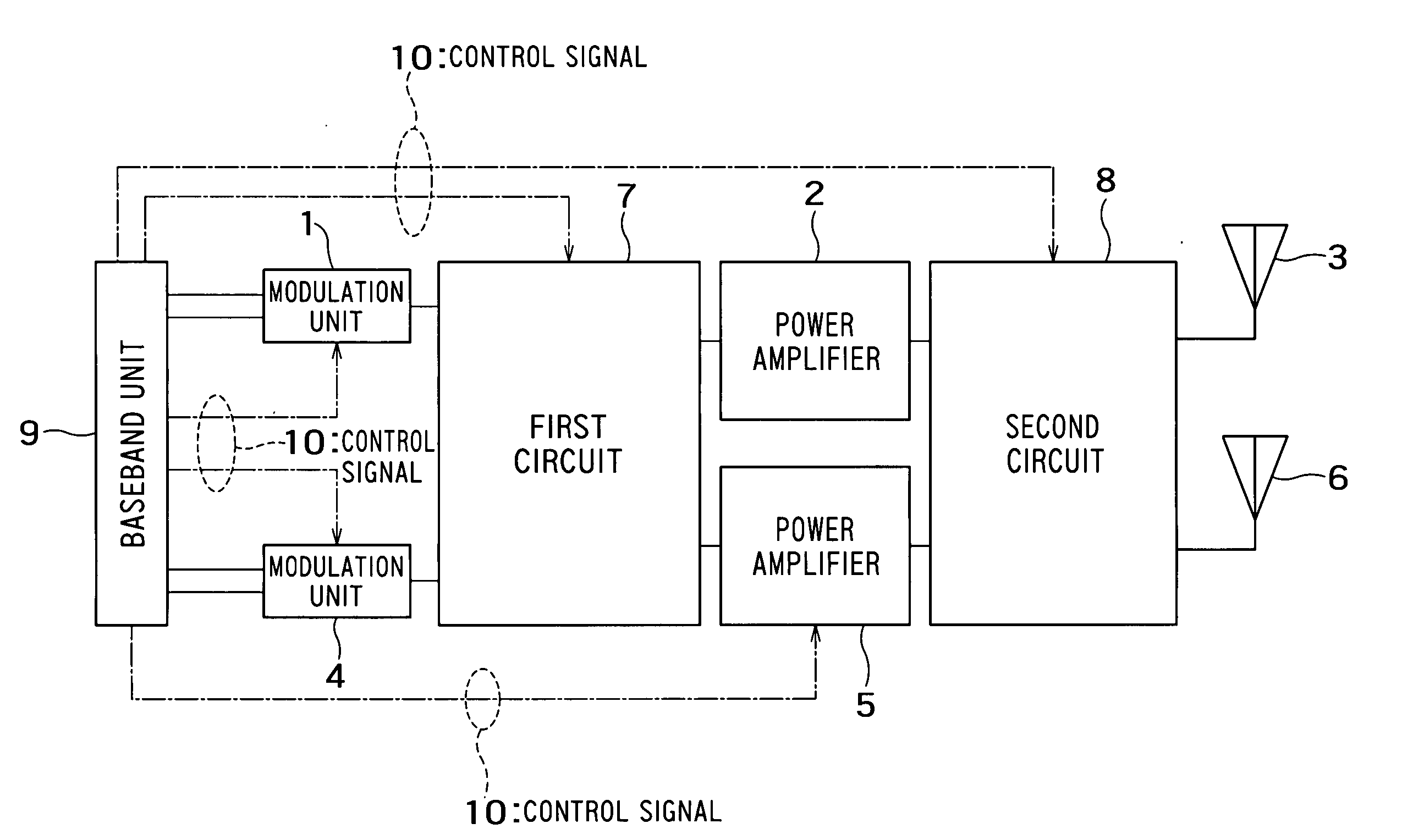
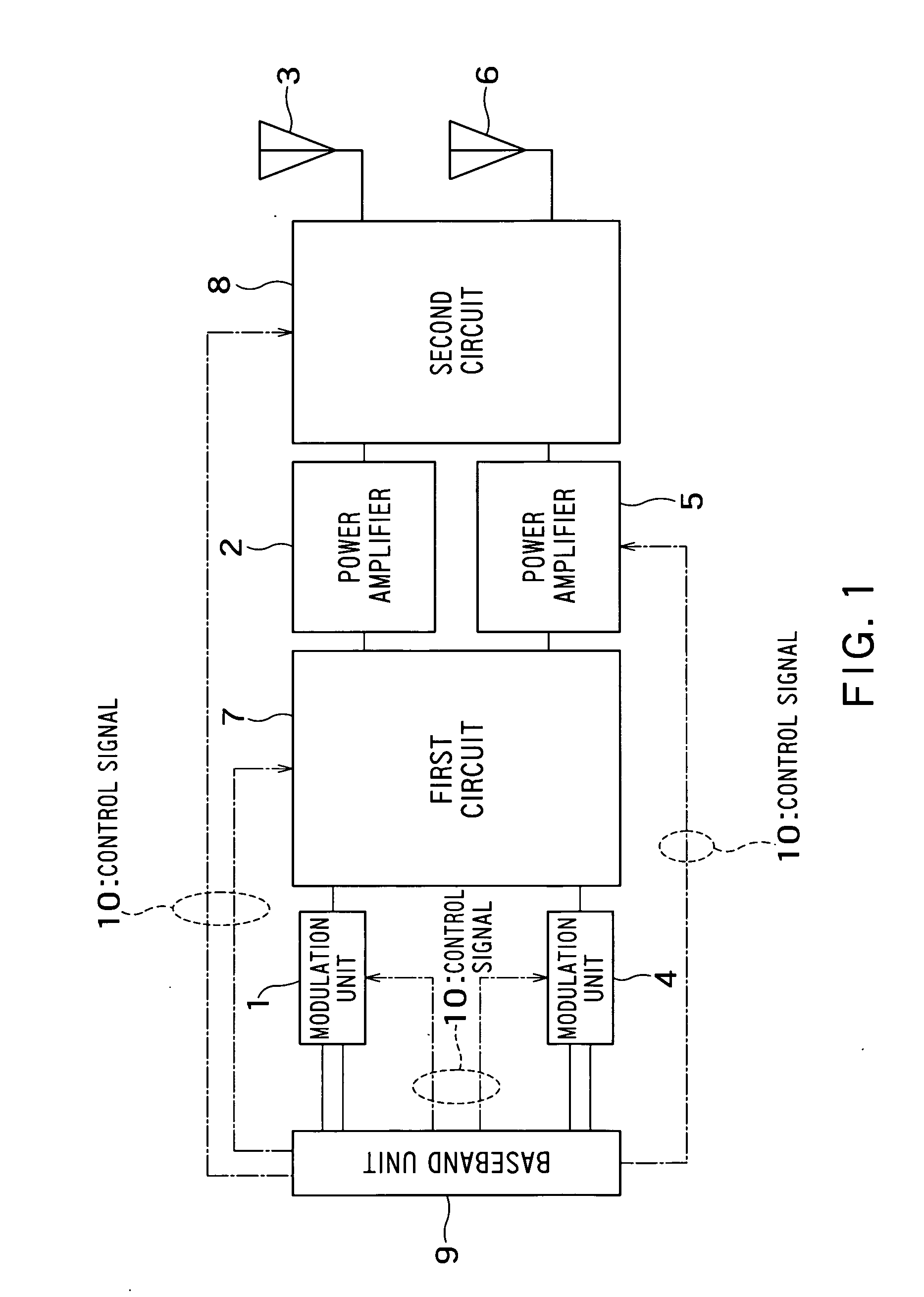
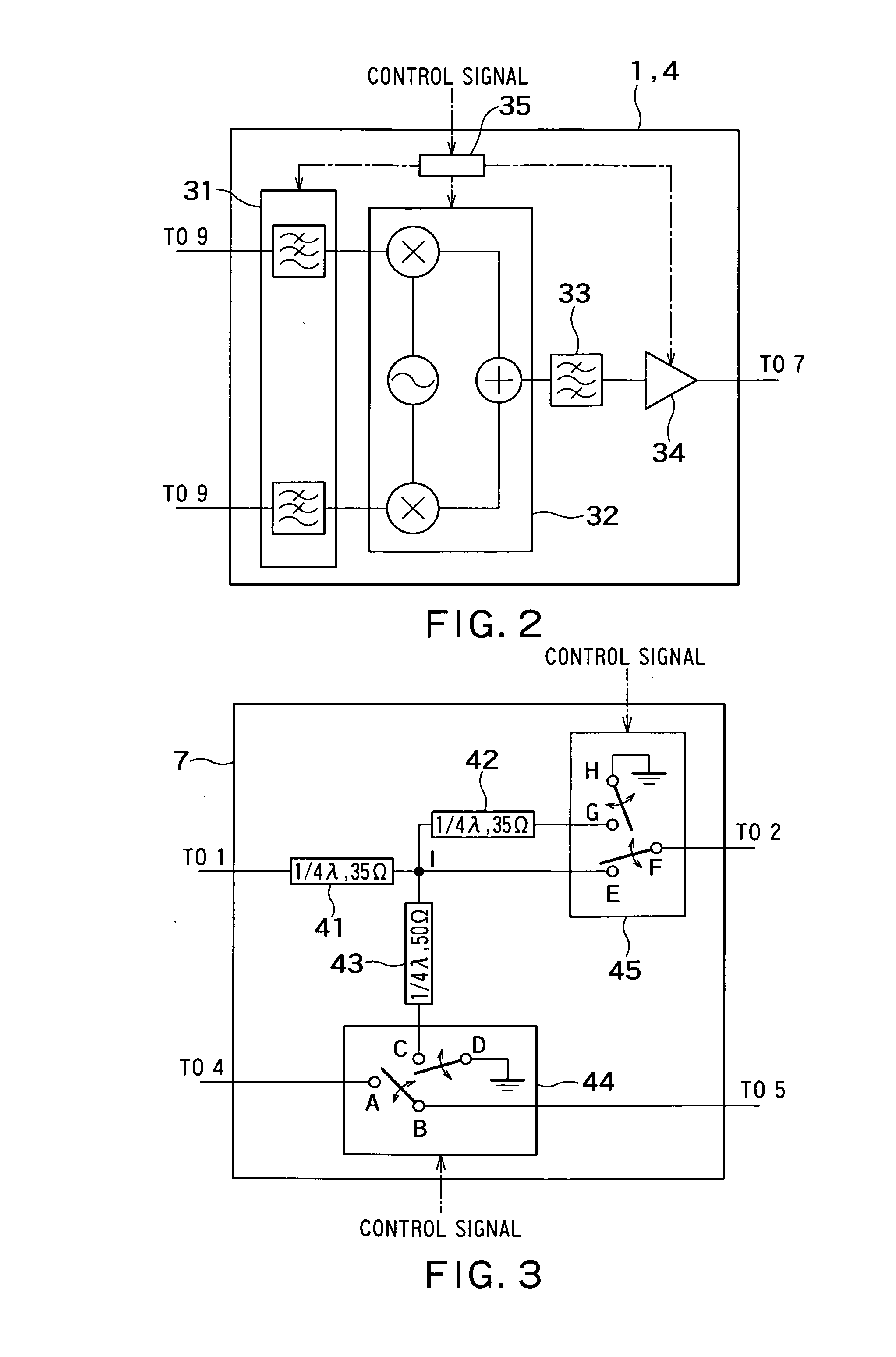
[0022] According to an aspect of the present invention, there is provided with a wireless transmitter comprising: a first modulation unit configured to modulate first input signal to first modulated signal; a second modulation unit configured to modulate second input signal to second modulated signal; a first amplifier configured to amplify the first modulated signal and output first amplified signal; a second amplifier configured to amplify the second modulated signal and output second amplified signal; a first antenna configured to radiate first amplified signal; a second antenna configured to radiate second amplified signal; a first path which conducts the first modulated signal to the first amplifier and conducts the second modulated signal to the second amplifier; a second path which divides the first modulated signal to conduct first divided signal to the first amplifier and second divided signal to the second amplifier; a first path changeover unit which conducts the first modulated signal and second modulated signal, to the first path or the second path selectively; a third path which conducts the first amplified signal to the first antenna, and conducts the second amplified signal to the second antenna; a fourth path which generates combined signal which is sum of the first amplified signal and the second amplified signal at a combining point, and conducts the combined signal to the first or second antenna; an impedance conversion unit which converts impedance between the first amplifier and the combining point; a second path changeover unit which conducts the first amplified signal and second amplified signal, to the third path or the fourth path selectively; and a control unit configured to set the first path changeover unit to conduct the first modulated signal and second modulated signal to the first path at the time to set the second path changeover unit to conduct the first amplified signal and second amplified signal to the third path, and configured to set the first path changeover unit to conduct the first modulated signal and second modulated signal to the second path at the time to set the second path changeover unit to conduct the first amplified signal and second amplified signal to the fourth path.
[0023] According to an aspect of the present invention, there is provided with an amplifier comprising: a first power amplifier configured to input a first input signal to obtain a first power amplification signal; a second power amplifier configured to input a second input signal to obtain a second power amplification signal; a divider configured to input a part of the first input signal into the second power amplifier as the second input signal, responsively to an external control signal; an impedance conversion unit configured to impedance-convert a supplied signal; a combiner configured to combine a signal impedance-converted by the impedance conversion unit and the second power amplification signal; and a selector configured to select supplying the first power amplification signal for the impedance conversion unit to output a combine signal obtained by the combiner, responsively to the external control signal, or outputting the first power amplification signal and the second power amplification signal respectively.

Problems solved by technology

In general, as the output level approaches a saturation output level in power amplifiers, the operation efficiency rises, but the distortion characteristics are degraded.
On the other hand, as the output level becomes lower than the saturation level, the distortion characteristics are improved, but the operation efficiency is degraded.
In a MIMO transmitter which operates in non-MIMO as described above, therefore, the power amplifier operate inefficiently when executing MIMO transmission.
Furthermore, the distortion level of the first power amplifier must be −30 dBc or less.
Since the backoff level of the power amplifier at the time of MIMO transmission increases, a problem that the operation efficiency is degraded and the power dissipation of the transmitter increases occurs.
If it is made possible to transmit a signal by using only one transmitting series in the transmitter for MIMO transmission, it becomes necessary to provide power amplifiers having a high saturation output level, resulting in a problem of increased power dissipation of the transmitter at the time of MIMO transmission.

Method used


Image

  • Wireless transmitter and amplifier
  • Wireless transmitter and amplifier
  • Wireless transmitter and amplifier

Examples


Embodiment Construction

[0040] First, how the present inventors have made the present invention will now be described.

[0041] As a technique for reducing efficiency degradation in backoff operation of the amplifier described in BACKGROUND OF THE INVENTION, the Doherty amplifier described in, for example, “High-Linearity RF Amplifier Design” written by Peter B. Kenington is known.

[0042] The Doherty amplifier includes a main amplifier, a sub amplifier, a power divider which divides power between the main amplifier and the sub amplifier, an impedance conversion circuit which converts load impedance for the main amplifier, a phase adjustment circuit which adjusts a phase of a signal output from the sub amplifier, and a power combiner which combines outputs of the main amplifier and the sub amplifier. FIG. 8 shows a configuration example of a Doherty amplifier including one main amplifier and one sub amplifier. In FIG. 8, 81 denotes a power divider, 82 a power combiner, 83 a main amplifier, 84 a sub amplifier,...


PUM


Abstract

There is provided with an amplifier comprising: first and second power amplifiers; a first path configured to output first and second input signals to the first and second power amplifiers; a second path configured to divide a first input signal, output one of divided signals to the first power amplifier and output the other divided signal to the second power amplifier; a first path changeover unit configured to change over the first and second paths; a third path configured to output first and second power amplified signals from the first and second power amplifiers; a fourth path configured to combines a first power amplified signal through an impedance conversion unit from the first power amplifier and a second power amplified signal from the second power amplifier at a combining point and output a combined signal; and a second path changeover unit configured to changeover the third and fourth paths.

Description

CROSS-REFERENCE TO RELATED APPLICATIONS [0001] This application claims the benefit of priority under 35USC §119 to Japanese Patent Application No. 2005-97911 filed on Mar. 30, 2005, the entire contents of which are incorporated herein by reference. BACKGROUND OF THE INVENTION [0002] 1. Field of the Invention [0003] The present invention relates to a wireless transmitter and amplifier to be used in a wireless communication system. [0004] 2. Description of the Background [0005] In recent years, various techniques have been proposed to improve the data transmission rate in wireless communication systems. One of them is a technique called MIMO (Multi-Input Multi-Output). [0006] The MIMO is a technique of transmitting a radio wave by using a plurality of analog transmitting series each including an antenna and receiving a radio wave by using a plurality of receiving series in the same way. The transmission rate can be increased using a phenomenon called multipath fading that a radio wave...

Claims


Application Information

Patent Timeline
Patent Type & Authority Applications(United States)
IPC IPC(8): H04B1/02H04B1/66
CPCH03F2200/111H03F2200/423H03F2200/429H04B1/0483H03F3/72H03F1/0288H03F3/24H03F3/602H04B2001/0408
Inventor KATO, TAKAYUKIYOSHIDA, HIROSHISETO, ICHIROYAMAGUCHI, KEIICHI
Owner KK TOSHIBA
Why Eureka
Try Eureka