Reflecting photonic concentrator

a technology of reflectors and concentrators, applied in the field of solar energy concentration, optics, power systems, etc., can solve the problems of not providing for the use of stationary reflectors, the time before investment in such technologies is returned, and the concentration of incident solar energy cannot be provided. achieve the effect of maximizing energy concentration, low architectural profile and optimizing device efficiency

Inactive Publication Date: 2006-11-09
ASCENDANT ENERGY COMPANY
View PDF44 Cites 33 Cited by
  • Summary
  • Abstract
  • Description
  • Claims
  • Application Information

AI Technical Summary

Benefits of technology

[0006] Accordingly, it is an object of the present invention to provide a reflecting concentrator assembly that is cost-competitive with conventional energy sources. It is another object of the present invention to provide a reflecting concentrator assembly that achieves concentration multiplier effects sufficient to attain optimal device efficiency.
[0007] It is a further object of the present invention to provide a reflecting concentrator assembly that presents a low architectural profile, yet be capable of tracking the sun both as it proceeds across the sky throughout the day and throughout the seasons.
[0008] It is yet another object of the present invention to provide a reflecting concentrator assembly that does not require the use of complicated internal adjustments in order to maximize energy concentration.
[0009] The present invention is a linearly reflecting trough concentrator with asymmetrical geometry that realizes 7× geometric concentration with trough depth comparable to prior art parabolic trough concentrators. The concentrator assembly of the present invention requires less depth to provide a lower profile device that more readily integrates with building applications and that is more compact for space applications, e.g. satellite solar power. The concentrator assembly evenly distributes reflected energy to avoid the creation of “hot spots” on the target concentration areas that are oriented in a vertical or near vertical plane. Also, the assembly may be scaled to allow greater degrees of concentration by increasing the width of the concentration area without significantly increasing the depth.

Problems solved by technology

However, although safe and clean, such systems typically are not very efficient and therefore often require significant time before investment in such technologies is returned.
These patents require rotation of the arrayed reflectors and do not provide for the use of stationary reflectors.
However, this reference does not provide for the concentration of incident solar energy.
None of these systems, however, create the desired multiplier effect necessary to attain optimal device efficiency.

Method used


Image

  • Reflecting photonic concentrator
  • Reflecting photonic concentrator
  • Reflecting photonic concentrator

Examples


first embodiment

[0018] In a first embodiment, the present invention provides a reflective concentrator assembly that uses the Fresnel lens principle to describe the negative, inside profile of two refractive lenses that are superimposed, or interleaved, over one another. Where the first set of reflective surfaces are slopes having their own reflective target, the second set of reflective surfaces are reliefs that allow the first three slopes to be formed contiguously by a reflective material or substrate. Further, the relief surfaces do not interfere with the reflective pathway of photonic energy toward the target area when that photonic energy strikes the heliostatic array at an incident angle of 90 degrees. Because one embodiment of the concentrator assembly is symmetrical, the inverse is true where the second set of reflective surfaces are slopes having their own target, and the first set of reflective surfaces are reliefs.

second embodiment

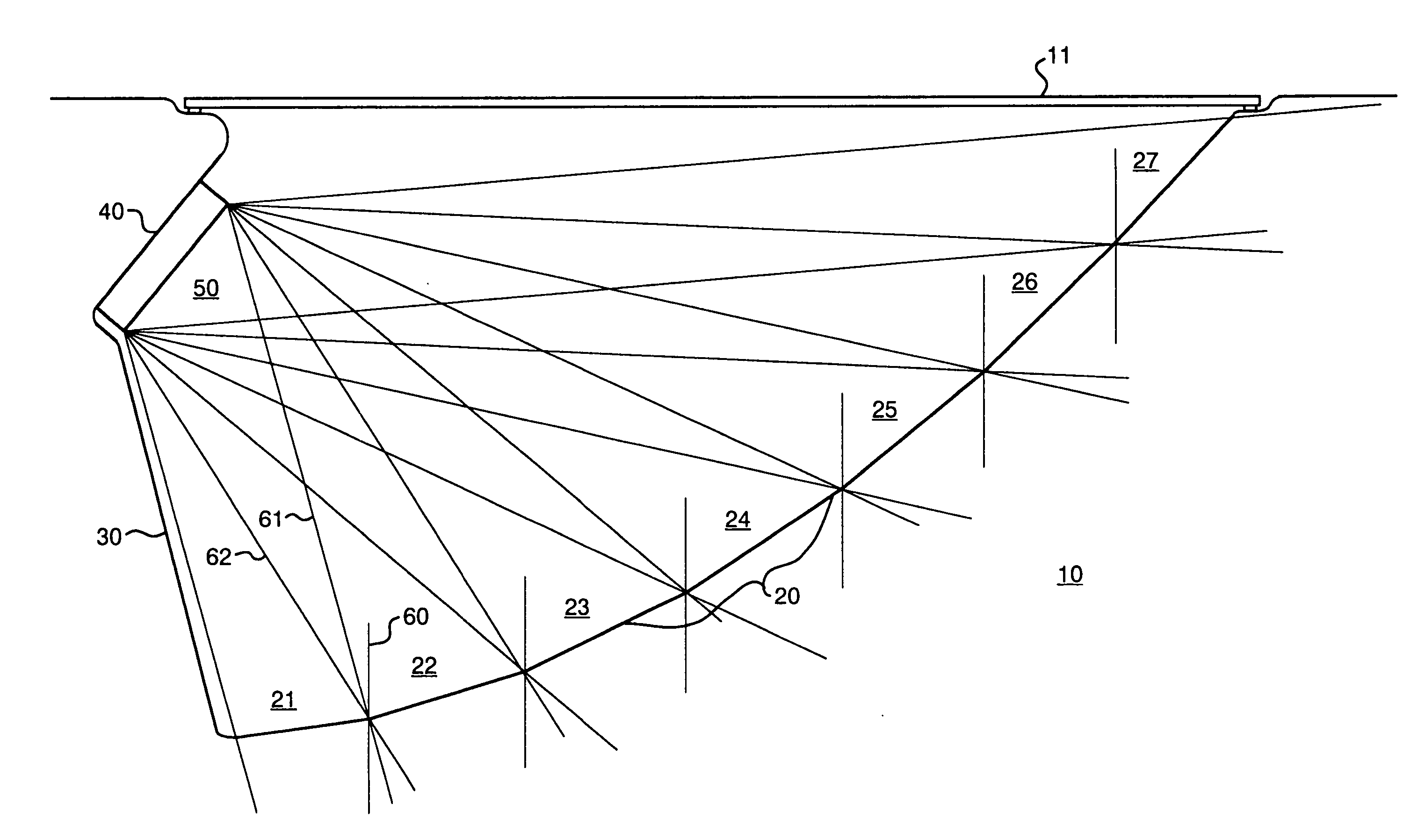
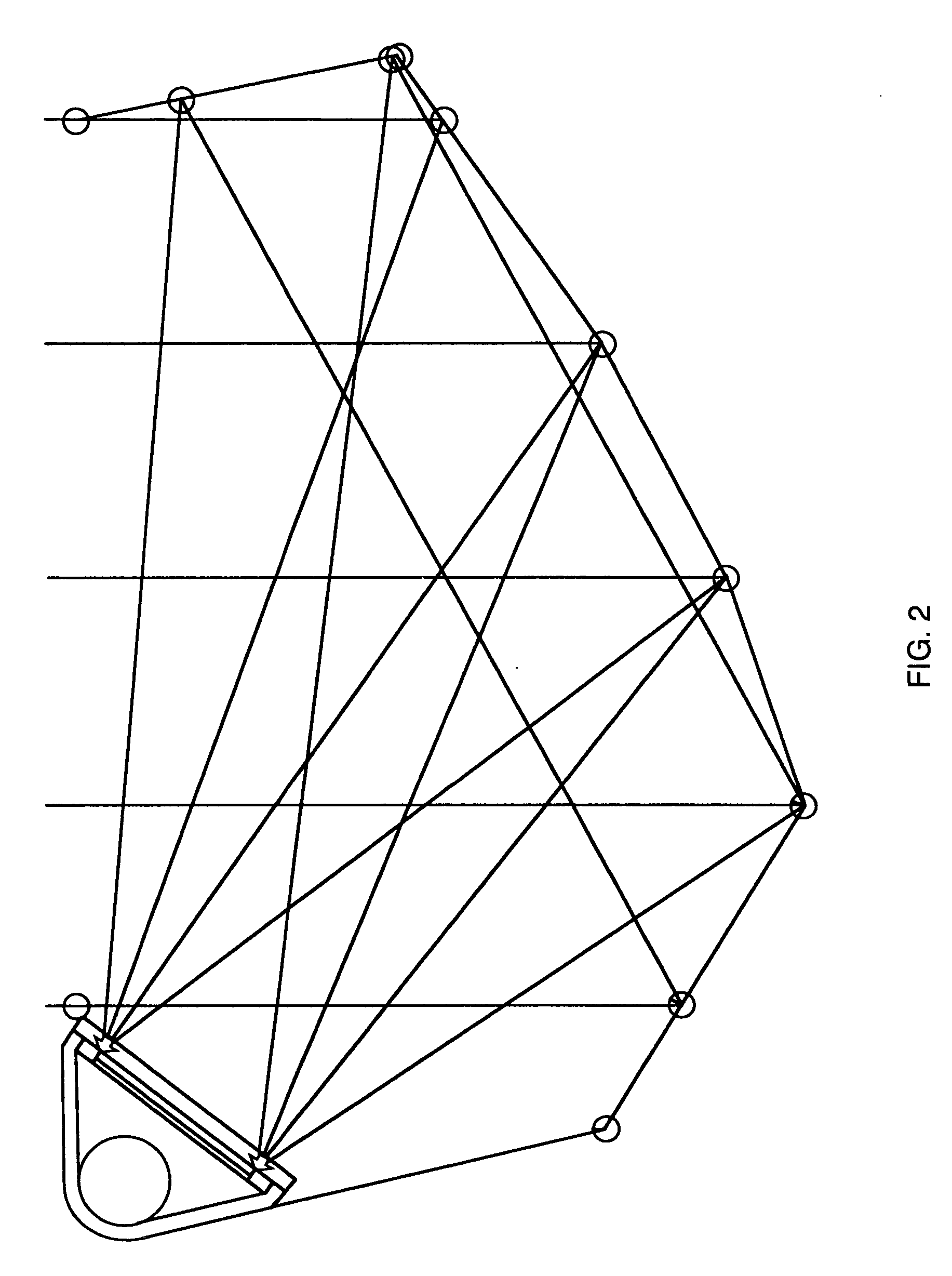
[0019]FIG. 1 shows the concentrator assembly of the present invention and depicts the reflective pathway of energy striking the heliostatic array at incident angle of 90 degrees and being reflected toward the two target areas. It is contemplated that these two target areas may comprise photonic transducers or receiving devices. In a second embodiment, a reflective projector may be used in conjunction with the heliostatic array. The reflective surface of the projector is designed to receive photonic energy arriving at a plurality of incident angles from the second set of reflective surfaces of the concentrator, and to evenly reflect and distribute that energy to the first target area described above.

[0020]FIG. 2 represents the concentrator assembly with the reflective projector attached to the right side of the heliostatic array and depicts the path of photonic energy striking the heliostatic array at incident angle of 90 degrees. While a first set of light rays strike the first set ...

third embodiment

[0023] In the present invention, shown in FIG. 3, concentrating reflector 10 comprises reflective surface area 20, relief plane 30, and vertically oriented sidewall 40 for mounting solar receiver 50. In a preferred embodiment, wherein reflective surface 20 is faceted and non-imaging, a parabolic shape is described having a curve formed of large intervals to form the single heliostat. When the profile of the single reflective surface 20 is joined to relief plane 30, the negative profile, i.e., the concave inside edge, is described for a single convex slope-relief Fresnel lens interval.

[0024] In a Fresnel lens, the convex thickness of a lens may be reduced by dividing the arc of the lens into segments and then flattening the top of each curved segments onto the same plane. The segment's curvature is the slope, and the interval segment necessary to eliminate thickness and join each slope is the relief. The preferred embodiment of the disclosed invention is derived from embodiments havi...


PUM


Abstract

A linearly reflecting trough concentrator that receives spectral energy, preferably visible and near-infrared solar energy spectra, and linearly reflects that energy onto a smaller area on one side of the device, thereby concentrating the energy. The linearly reflecting trough concentrator has the geometry of a single slope-relief interval in a Fresnel lens, and in preferred embodiment comprises an array of heliostatic facets connected continuously to form the base of the trough, a non-imaging focal point where a photonic receiver is located, and a relief surface to connect the heliostatic array to the receiver location. When spectral energy enters the trough at an angle normal to the array's horizontal reference, the concentrator linearly reflects energy to one side of the device where an energy receiver is mounted. The concentrator comprises an array of heliostats oriented according to the negative profile of two interleaved linear Fresnel lens, where the slope of one is the relief of the other. The concentrator reflects energy above and to each side of the device. Optionally using a reflecting projector on one side of the device, energy is then doubly concentrated to the other side. The device offers higher concentration ratios with an equivalent trough depth than prior art reflective trough concentrators. The device requires less depth and offers a lower-profile than prior art reflecting concentrators with the same degree of concentration.

Description

TECHNICAL FIELD [0001] The present invention relates generally to solar energy concentration, optics, and power systems, and more specifically to a reflecting photonic concentrator system using a heliostatic array. BACKGROUND OF THE INVENTION [0002] Capturing solar radiation energy for conversion to heat and electricity has become a significant alternate energy source. However, although safe and clean, such systems typically are not very efficient and therefore often require significant time before investment in such technologies is returned. Attempts have been made to concentrate solar radiation energy to improve the efficiency of solar energy systems. Prior art linear trough concentrators that track the light source, especially the sun, are mostly parabolic in cross-section and require significant depths to realize higher degrees of concentration. [0003] For solar thermal applications where a fluid is superheated in a pipe, the width of the pipe does not require a significant dept...

Claims


Application Information

Patent Timeline
Patent Type & Authority Applications(United States)
IPC IPC(8): F24J2/38F24S23/71F24S23/79F24S50/20
CPCF24J2/1047F24J2/14G02B19/0033G02B19/0019G02B19/0042Y02E10/45F24S23/80F24S2023/874F24S23/74Y02E10/40
Inventor STRAKA, CHRISTOPHER W.
Owner ASCENDANT ENERGY COMPANY
Why Eureka
Try Eureka