Method of manufacturing curved composite structural elements

a composite structural element and curved technology, applied in the field of composite structures, can solve the problems of composite material design and unidirectional fibers not following the contour of the structural member

Inactive Publication Date: 2006-11-09
THE BOEING CO
View PDF63 Cites 136 Cited by
  • Summary
  • Abstract
  • Description
  • Claims
  • Application Information

AI Technical Summary

Problems solved by technology

However, the composite material designs can have the disadvantage that the unidirectional fibers do not follow the contour of the structural member.

Method used


Image

  • Method of manufacturing curved composite structural elements
  • Method of manufacturing curved composite structural elements
  • Method of manufacturing curved composite structural elements

Examples


Embodiment Construction

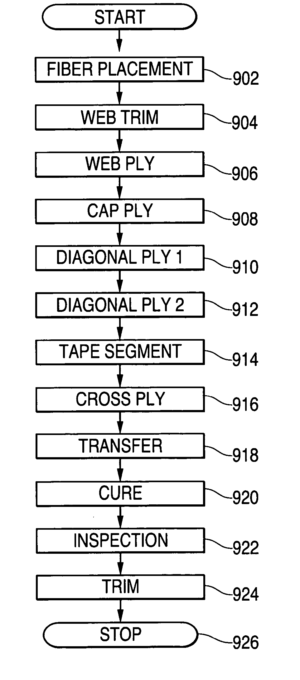
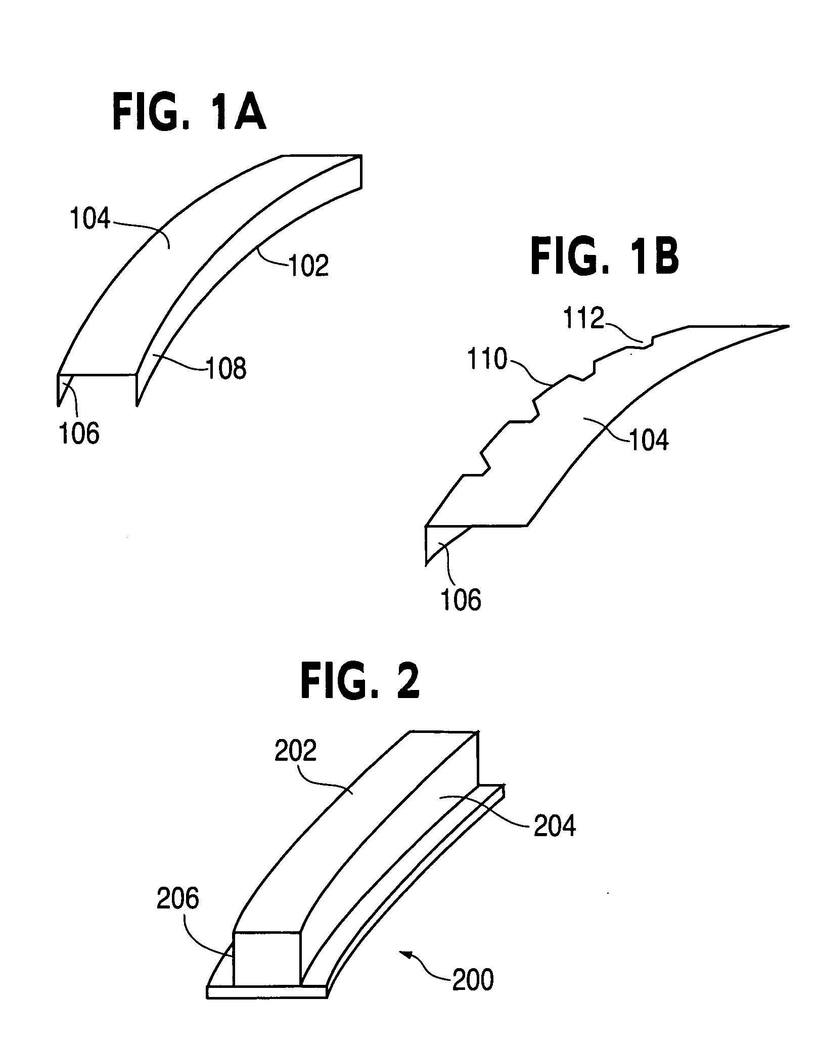
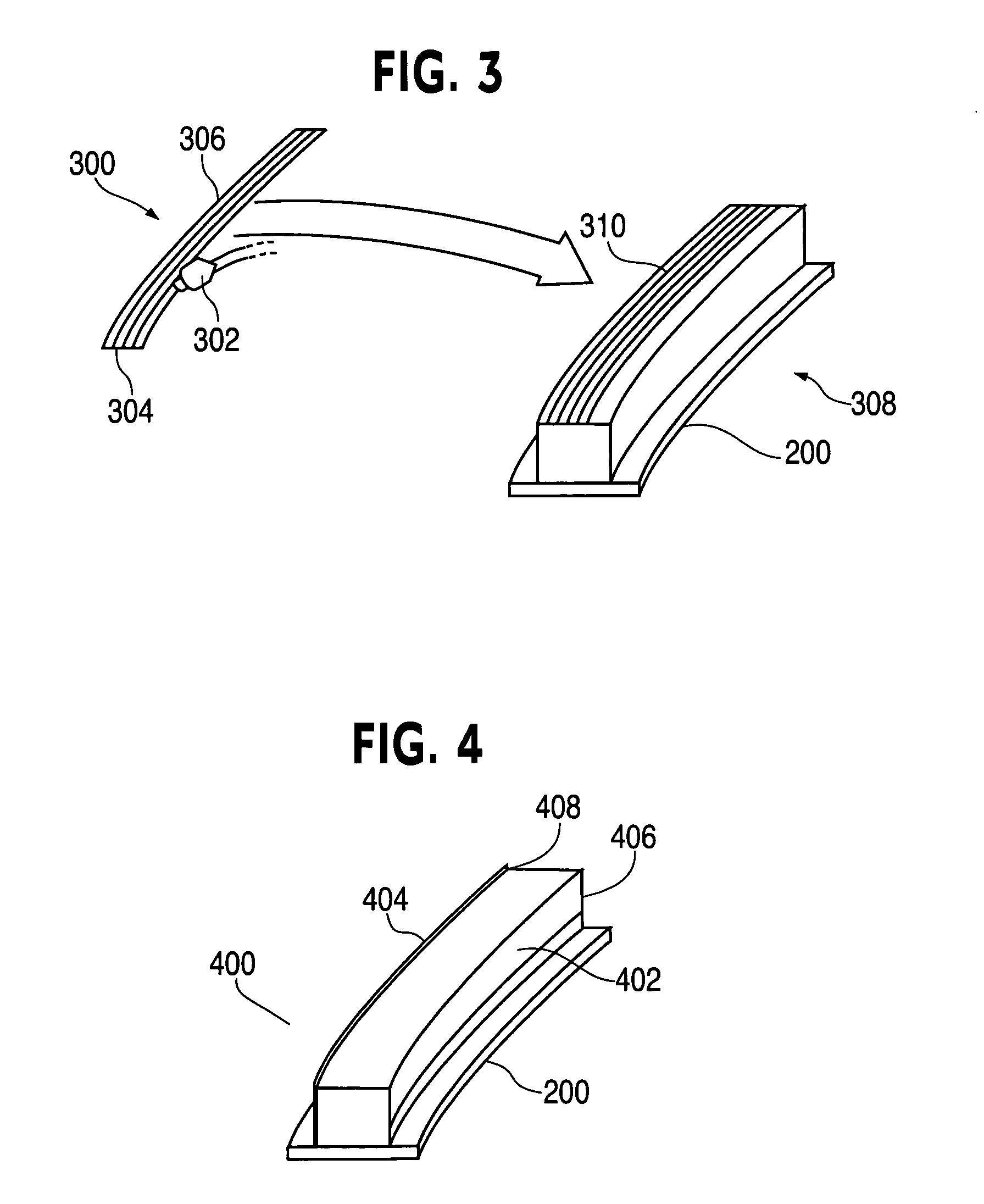
[0024] An embodiment in accordance with the present disclosure provides a method of manufacturing curved composite structural elements. The method can include fabricating a composite curved web ply using an advanced fiber placement (AFP) machine such that the fiber orientation of the composite material is substantially aligned with the curvature of the structural element. The web ply can then be trimmed and laid up on a manufacturing tool having a curved surface to match the shape of the web ply.

[0025] The method also can include laying up a diagonal ply of composite fabric with the fabric fibers oriented at 45 degrees from a tangent of the centerline of the curved surface. The method further can include laying up a cross ply composed of composite tape segments with the tape fibers oriented at a right angle to the tangent of the centerline of the curved surface. In addition, one or both edges of the diagonal ply and the cross ply may be folded over a side of the manufacturing tool ...


PUM

PropertyMeasurementUnit
widthsaaaaaaaaaa
widthsaaaaaaaaaa
angleaaaaaaaaaa

Abstract

A method of manufacturing curved composite structural elements can include fabricating a web ply in a flat curve over a removable substrate and laying up the ply on a curved web surface of a manufacturing tool. The method also can include laying up a diagonal ply with fibers oriented at + / −45° from the centerline of the web surface. The method further can include cutting a unidirectional composite tape into segments and laying up the tape segments to form a cross ply with a fiber orientation normal to the centerline of the web surface. One or both edges of the diagonal and cross plies may be folded over one or two sides of the manufacturing tool to form one or two flange surfaces. Additionally, a cap ply can be laid up on one or both flange surfaces using composite tape. The structural element layup can then be inspected and any excess composite material can be trimmed away.

Description

FIELD OF THE INVENTION [0001] The present disclosure relates generally to composite structures. More particularly, the present disclosure relates to manufacturing load-carrying structural elements from composite materials. BACKGROUND OF THE INVENTION [0002] Composite materials have been used increasingly in a variety of industries, including the automotive, marine and aerospace industries. Composite materials have been used to produce nonload-carrying structures, such as boat hulls or automobile body panels. Composite materials have also been applied in the manufacture of load-carrying structures, such as pressure vessels and aircraft fuselages. [0003] Composite materials especially have application in the design of structural members carrying tensile loads. Composite materials used in these designs include strong fibrous materials, such as carbon, aramid, glass or quartz, bonded together with a resin material, such as an epoxy. Such materials can have the advantage of a high tensil...

Claims


Application Information

Patent Timeline
Patent Type & Authority Applications(United States)
IPC IPC(8): B29C70/30B32B37/00
CPCB29C70/342Y10T156/1067B29C70/386B29C70/48B29C70/545B29K2063/00B29K2067/00B29K2307/00B29K2309/10B29L2031/003B29L2031/3082B32B38/0004B32B38/04B32B38/1808B32B38/1816B32B38/1858Y10T156/108Y10T156/1051Y10T156/1075Y10T156/1002B29C70/382B29C43/12
Inventor BROWN, TODD A.FRIDDELL, STEPHEN DOUGLASHARRIS, CHRISTOPHER G.MODIN, ANDREW E.
Owner THE BOEING CO
Why Eureka
Try Eureka