Large area lighting system

a technology of large area lighting and large beam, which is applied in the field of large area lighting systems, can solve the problems that unwanted light cannot directly pass between the light baffle and the light baffle, and achieve the effects of effective light shielding, low effective projected area (epa) level, and reduced spillag

Inactive Publication Date: 2006-11-09
CHM INDS
View PDF13 Cites 10 Cited by
  • Summary
  • Abstract
  • Description
  • Claims
  • Application Information

AI Technical Summary

Benefits of technology

[0007] The present invention provides an improved large area lighting system. In a preferred embodiment light spillage is minimized or eliminated for an entire lighting unit, rather than just individual fixtures. The improved lighting system provides a light baffle designed to block light spillage from the entire light fixture and maintains a very low effective projected area (EPA) level.
[0008] In accordance with an important aspect of the invention, a ‘slat’ style light baffle is provided. The slats are preferably positioned to extend horizontally, thus providing, for example, the best combination of sufficient light delivery, effective light shielding and low EPA. One preferred embodiment provides, for example, a light baffle which may be adjusted in different orientations to increase light delivery to a subject lighting area while minimizing light spillage into a protected area, decreasing light pollution, eliminating unnecessary sky glow and maintaining a low EPA. The orientation of the slat type baffles allows light to selectively pass through or be diffused by the light baffle to the subject lighting area. Conversely, unwanted light cannot directly pass between the light baffle to the protected area, such as a residential area.
[0009] In accordance with another aspect of the invention, a preferred embodiment is fully customizable and may be retrofitted into existing lighting systems. Different lengths of slats may be provided to increase light delivery to the subject lighting area or, for example, decrease or eliminate light delivery to the protected area. Slats may be easily exchanged, added on to or removed from the light baffle. In addition, a preferred embodiment may be con

Problems solved by technology

Conversely, unwanted light cannot directly pass between the l

Method used


Image

  • Large area lighting system
  • Large area lighting system
  • Large area lighting system

Examples


Embodiment Construction

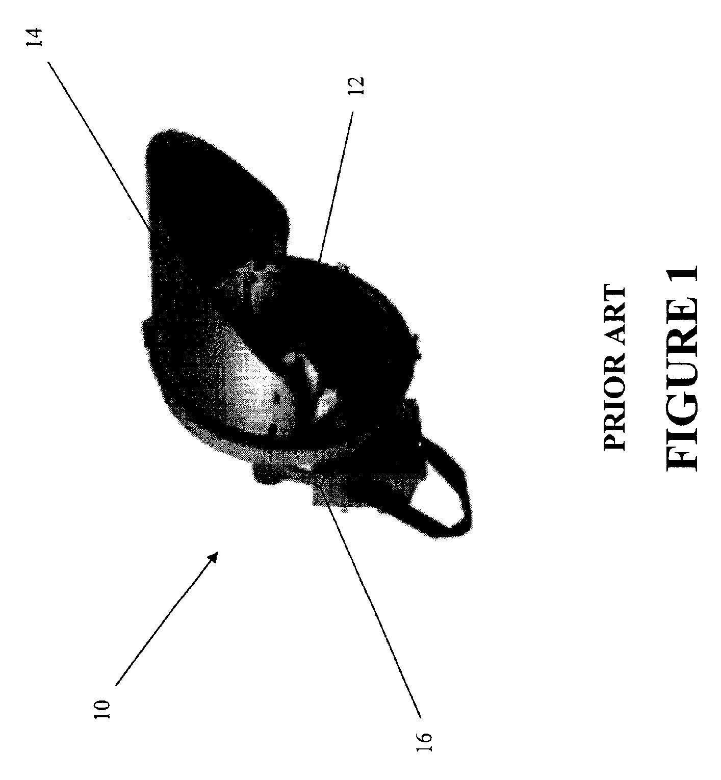
[0023] While the construction and use of preferred embodiments is discussed in detail below, it will be appreciated that the specific embodiments described do not limit the scope of the invention.

[0024] As mentioned earlier, large area lighting systems known in the art “spill” light into protected areas such as residential areas. For example, prior art lighting systems, such as lighting system 10, depicted in FIG. 1, fail to protect areas from unwanted light trespass. Lighting system 10 generally includes a lighting fixture 12, a shield 14 and a light base 16. Although the concept is widely adopted in the art, shield 14 fails to prevent light from “spilling” into protected areas. Often times, lighting system 10 and other large area lighting systems known in the art increase the overall effective projected area (EPA) of the structure of the system. Thus, existing systems often require, for example, stronger, more expensive poles and other support structures to accommodate higher EPA...


PUM


Abstract

A large area lighting system, adapted for high mast highway or stadium lighting, for example, includes one or more elongated frames supporting plural light fixtures and elongated light baffles comprising respective sets of spaced apart slats. The respective sets of slats are supported on elongated rods connected to light fixture frame members and the slats are separated by spacers sleeved over the rods. The slats may be oriented at various angles by manual or motor driven adjustment to control the light projection from the lighting system. The slats may also be non-reflective or provided with a mirrored finish to effect control of light projection and/or diffusion.

Description

BACKGROUND [0001] The present invention relates to the general field of lighting systems, and in particular, to large area lighting systems. [0002] Large area lighting systems provide various levels of illumination for a variety of applications while minimizing ground level obstructions. Large area lighting systems are often used to illuminate large areas such as highways and stadiums. In densely populated areas, such large area lighting systems tend to “spill” light into nearby residential areas and thus create a nuisance for the residents. Light spillage also contributes to other problems, such as increased light pollution and sky glow. As a result, many jurisdictions have enacted laws preventing the installation of large area lighting systems in close proximity to residential areas. [0003] There have been several unsuccessful attempts by those skilled in the art to address the light spillage issues referenced above. For example, prior art efforts have addressed light spillage pro...

Claims


Application Information

Patent Timeline
IPC IPC(8): F21V19/00
CPCF21S8/086F21V11/04F21W2131/105F21W2131/103F21W2111/06
Inventor GINSBURG, THOMAS A.
Owner CHM INDS
Why Eureka
Try Eureka