System and method for capturing data signals using a data strobe signal

a data strobe signal and data technology, applied in the field of digital devices, can solve the problems of line becoming heavily charged to a bias voltage, the critical timing of data strobe signals relative to the timing of data signals, and the variability in the quality of data strobe signals

Active Publication Date: 2006-11-09
MICRON TECH INC
View PDF26 Cites 30 Cited by
  • Summary
  • Abstract
  • Description
  • Claims
  • Application Information

AI Technical Summary

Problems solved by technology

As the speed of memory devices has continued to increase, the “data eye” has become smaller and smaller, thus making the timing of the data strobe signals relative to the timing of the data signals even more critical.
One difficulty that has been encountered in ensuring that data strobe signals transition at the proper time is the variability in quality of the data strobe signal.
The difficulty in transitioning the data strobe signal line when the line has been idle results from the line becoming heavily charged to a bias voltage, typically one-half the supply voltage VCC in a center tapped termination (“CTT”) system or the supply voltage VCC in an alternative (“VDD”) system.
However, as the operating speeds of memory devices continues to increase, it is becoming increasingly difficult for the data strobe signal to capture the first bit or two of data.
Unfortunately, it can be difficult to determine when valid data signals are being received, and it can be difficult to differentiate actual data strobe signals from data strobe signals occurring in the preamble.
This difficulty is e

Method used


Image

  • System and method for capturing data signals using a data strobe signal
  • System and method for capturing data signals using a data strobe signal
  • System and method for capturing data signals using a data strobe signal

Examples


Embodiment Construction

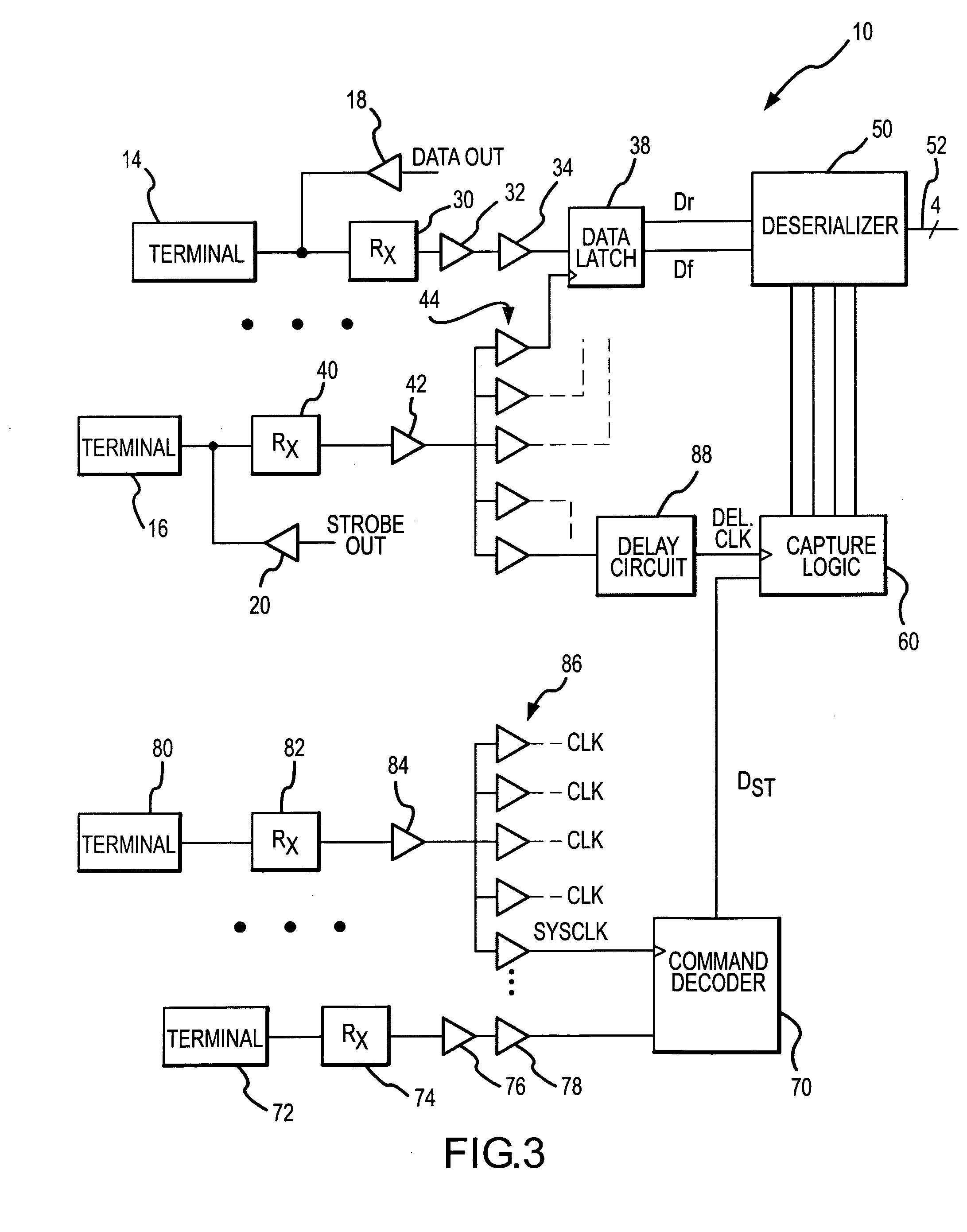
[0016] One embodiment of a system 10 for allowing write data signals to be captured in a memory device using a write data strobe signal is shown in FIG. 3. The system 10 includes several data bus terminals 14 (only one of which is shown in FIG. 3) and a terminal 16 receiving a write strobe signal. Write data signals corresponding to a bit of write data are applied to the data bus terminal 14, generally from a memory controller (not shown in FIG. 3). Read data signals corresponding to a bit of read data are coupled to the data bus terminal from internal circuitry (not shown in FIG. 3) through a data driver 18. Similarly, a read data strobe signal is coupled to the terminal 16 through a strobe driver 20.

[0017] The write data signals applied to the data bus terminal 14 are coupled through a receiver 30 and a pair of drivers 32, 34 to a data input of a data latch 38. The write strobe signal is coupled through a similar receiver 40 and a first driver 42. The driver 42 has sufficient dri...


PUM


Abstract

A signal capture system and method is used to capture a data signal using a data strobe signal having a preamble of strobe signal transitions. The system includes a data latch circuit receiving the data signal. The data latch circuit is clocked by transitions of the data strobe signal to capture respective bits of data corresponding to the data signal. A decoder receives a memory command signal and generates a data start signal after a delay period from receiving the memory command signal if the command signal corresponds to a read or a write command. The receipt of read or write command signals is used by a control circuit to identify the start of valid read or write data signals. The control circuit then outputs the captured data signals responsive to the data start signal, thereby ignoring the transitions in the preamble of the data strobe signal.

Description

TECHNICAL FIELD [0001] This invention relates to digital devices such as memory devices, and, more particularly, to a method and system for allowing digital data coupled between two devices to be accurately captured at the receiving device by a high-speed clock signal. BACKGROUND OF THE INVENTION [0002] Periodic digital signals are commonly used in a variety of electronic devices. Probably the most common type of periodic digital signals are clock signals that are typically used to establish the timing of a digital signal or the timing at which an operation is performed on a digital signal. For example, data signals are typically coupled to and from memory devices, such as synchronous dynamic random access memory (“SDRAM”) devices, in synchronism with a data strobe signal. The data strobe signal typically has a phase that is aligned with a system clock signal. Write data signals are typically coupled from the memory controller in synchronism with a write data strobe signal. The writ...

Claims


Application Information

Patent Timeline
IPC IPC(8): G11C8/00
CPCG11C7/1078G11C7/1087G11C7/1093G11C2207/107G11C7/222G11C11/4076G11C11/4096G11C7/22
Inventor CHOI, JOO S.JOHNSON, JAMES B.
Owner MICRON TECH INC
Why Eureka
Try Eureka