Nuclear voltaic cell

a voltaic cell and nuclear technology, applied in the direction of radiation electrical energy, reaction to electrical energy, radiation applications, etc., can solve the problems of no direct conversion method that is efficient and practical, and achieve the effects of small or no maintenance, large electrical energy generation, and small siz

a voltaic cell and nuclear technology, applied in the direction of radiation electrical energy, reaction to electrical energy, radiation applications, etc., can solve the problems of no direct conversion method that is efficient and practical, and achieve the effects of small or no maintenance, large electrical energy generation, and small siz

US20060251204A1Inactive Publication Date: 2006-11-09TSANG FRANCIS YU HEI +5

Image

  • Nuclear voltaic cell
  • Nuclear voltaic cell
  • Nuclear voltaic cell

Examples


Embodiment Construction

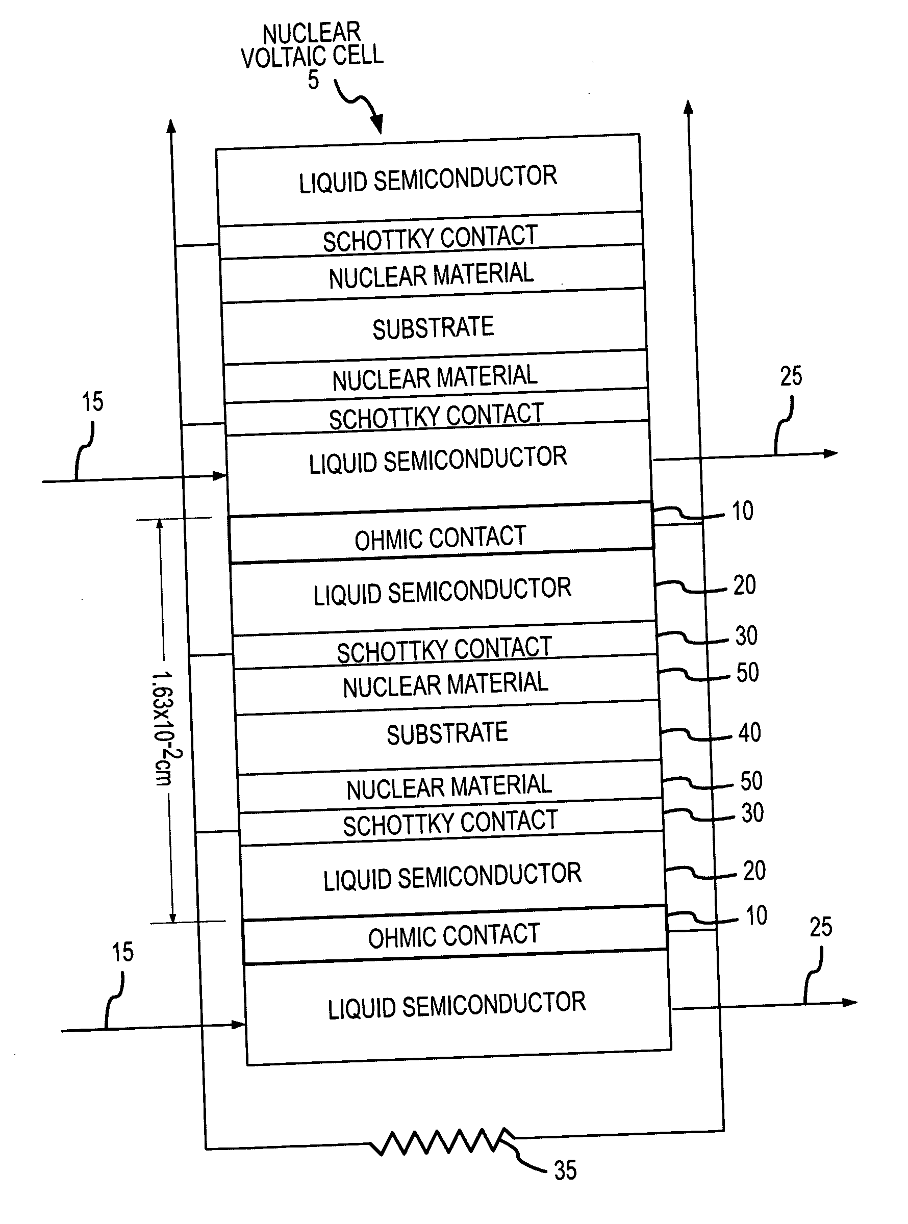
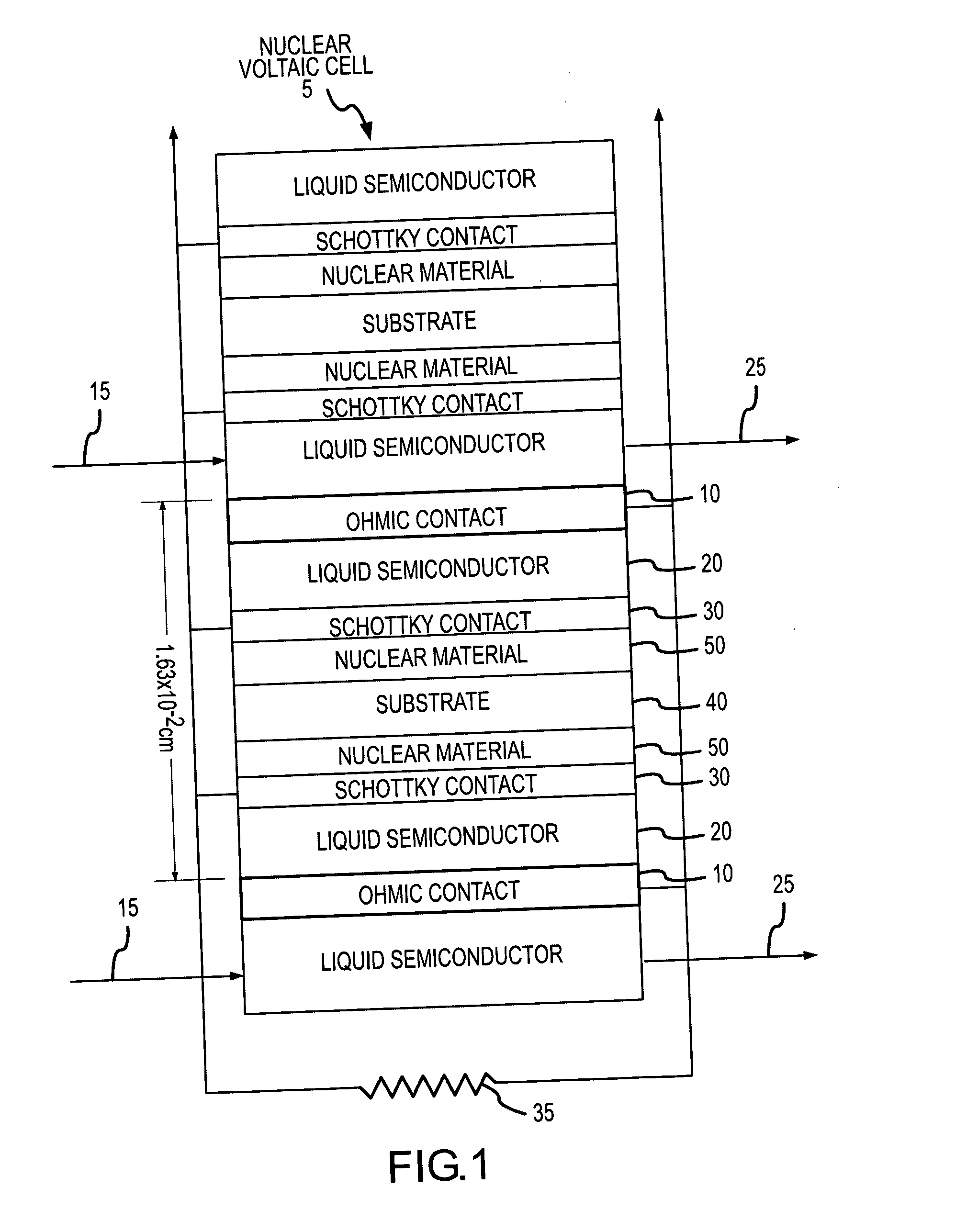
[0057]FIG. 1 shows a cross section through one embodiment of the Nuclear Voltaic Cell 5. In this embodiment, the Liquid Semiconductor 20 is sandwiched between two metal contacts; the Ohmic Contact 10 and the Schottky Contact 30. The device will also function if a low resistance contact is used in lieu of the Ohmic Contact 10. This may be necessary in the case that an ideal Ohmic Contact 10 is not readily available as a result of fundamental or practical reasons.

[0058] As shown in FIG. 1, the Liquid Semiconductor 20 is sandwiched between the two metal contacts, the Ohmic Contact 10 and the Schottky Contact 30. Furthermore, as shown in FIG. 1, the two metal contacts, the Ohmic Contact 10 and the Schottky Contact 30, form a channel through which the Liquid Semiconductor 20 may flow. In a preferred embodiment of the present invention, the Liquid Semiconductor 20 flows in the direction of the Arrow 15 into the channel between the Ohmic Contact 10 and the Schottky Contact 30 and then flo...


PUM

PropertyMeasurementUnit
average energyaaaaaaaaaa
metallicaaaaaaaaaa

Abstract

The invention describes a product and a method for generating electrical power directly from nuclear power. More particularly, the invention describes the use of a liquid semiconductor as a means for efficiently converting nuclear energy, either nuclear fission and / or radiation energy, directly into electrical energy. Direct conversion of nuclear energy to electrical energy is achieved by placing nuclear material in close proximity to a liquid semiconductor. Nuclear energy emitted from the nuclear material, in the form of fission fragments or radiation, enters the liquid semiconductor and creates electron-hole pairs. By using an appropriate electrical circuit an electrical load is applied and electrical energy generated as a result of the creation of the electron-hole pairs.

Description

CROSS REFERENCE TO RELATED APPLICATION [0001] This application is a divisional application of application Ser. No. 10 / 720,035 filed on Nov. 21, 2003 and titled “Nuclear Voltaic Cell,” which is incorporated herein by reference in its entirety.FIELD OF THE INVENTION [0002] The invention relates primarily to a method of and a device for generating electrical power directly from nuclear power, and more particularly to using liquid semiconductors as a means for efficiently converting nuclear energy, either nuclear fission and / or radiation energy, directly into electrical energy. BACKGROUND OF THE INVENTION [0003] Ever since the potential for generating electrical power from nuclear reactions was recognized, scientists have strived to devise the best methods of harnessing nuclear power and putting it to practical use. The main objectives of such research have been to create the most efficient methods of power conversion, power converters that can generate electrical power from nuclear pow...

Claims


Application Information

Patent Timeline
09 Nov 2006
Publication
US20060251204A1
IPC
G21D7/00; G21H1/04; H01M
CPC
G21H1/04; G21H5/00
Inventors
TSANG, FRANCIS YU-HEI; JUERGENS, TRISTAN DIETER