
Sheet transferring device and image forming device

a transfer device and a technology of forming device, applied in the direction of thin material processing, electrographic process apparatus, instruments, etc., can solve the problems of uniform transfer gap and unsatisfactory adjustment of transfer gap, and achieve uniform transfer gap

Inactive Publication Date: 2006-11-09
RICOH KK
View PDF12 Cites 9 Cited by
  • Summary
  • Abstract
  • Description
  • Claims
  • Application Information

AI Technical Summary

Benefits of technology

[0012] A preferred embodiment of the present invention may implement transferring plural sheets at a constant pitch in sequence with a high precision. According to an aspect of the present invention, precision of a constant pitch for continuously transferring plural sheets in sequence at a down stream side of the resist roller may be improved. An embodiment of the present invention may accurately position the sheet by the resist roller against image forming of an imaging system at the image forming device.
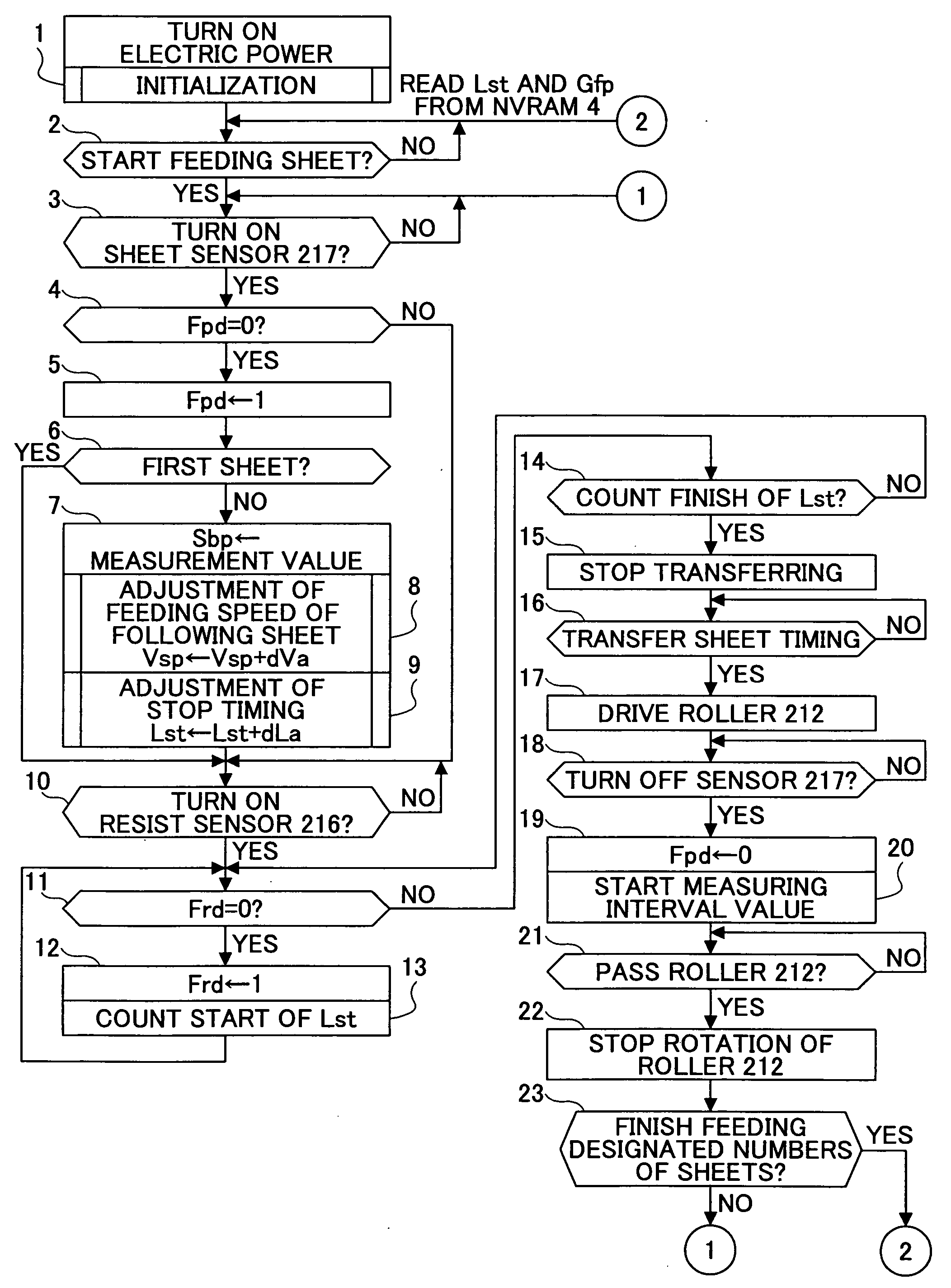
[0028] According to the above-mentioned sheet transferring device or image forming device, by performing feedback control based on the result of measurement of a transferring gap, it is possible to always secure a proper transferring gap even if a use condition is changed or variation with time of a transferring roller is generated. In addition, even if scattering is generated in the transferring gap for every single sheet, it is possible to maintain a uniform transferring gap.

Problems solved by technology

In addition, even if the transferring roller is new, when printing is performed continuously, a member of the transferring roller may expand or contract due to temperature change in the device, so that the designed speed may not be maintained.
In this case, even if transferring of the following sheet is adjusted by using the measuring result, since the transferring time is varied for every sheet, the transferring gap as a result of adjustment is not uniform.

Method used


Image

  • Sheet transferring device and image forming device
  • Sheet transferring device and image forming device
  • Sheet transferring device and image forming device

Examples


first embodiment

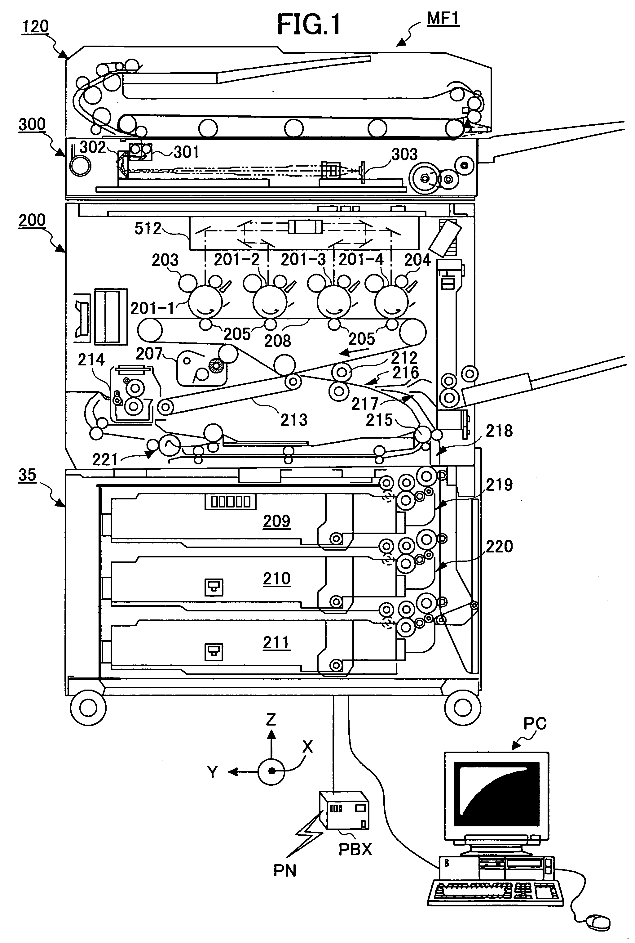
[0039]FIG. 1 is a cut-away vertical schematic view of a multi-function full color digital copier MF 1 of a first embodiment of the present invention. The full color copier MF1 includes units of, for example, an ADF (Automatic Document Feeder) 120, an operations board 10 (See FIG. 3), a color scanner 300, a color printer 200, and a paper feeding bank 35. A LAN (Local Area Network) to which a personal computer PC is connected is coupled to a system controller 501 (See FIG. 3) in the full color copier MF1. A facsimile controller 506 (See FIG. 3) in the full color copier MF1 can implement facsimile communication via a PBX (Private Branch Exchange) and PN (Public Network).

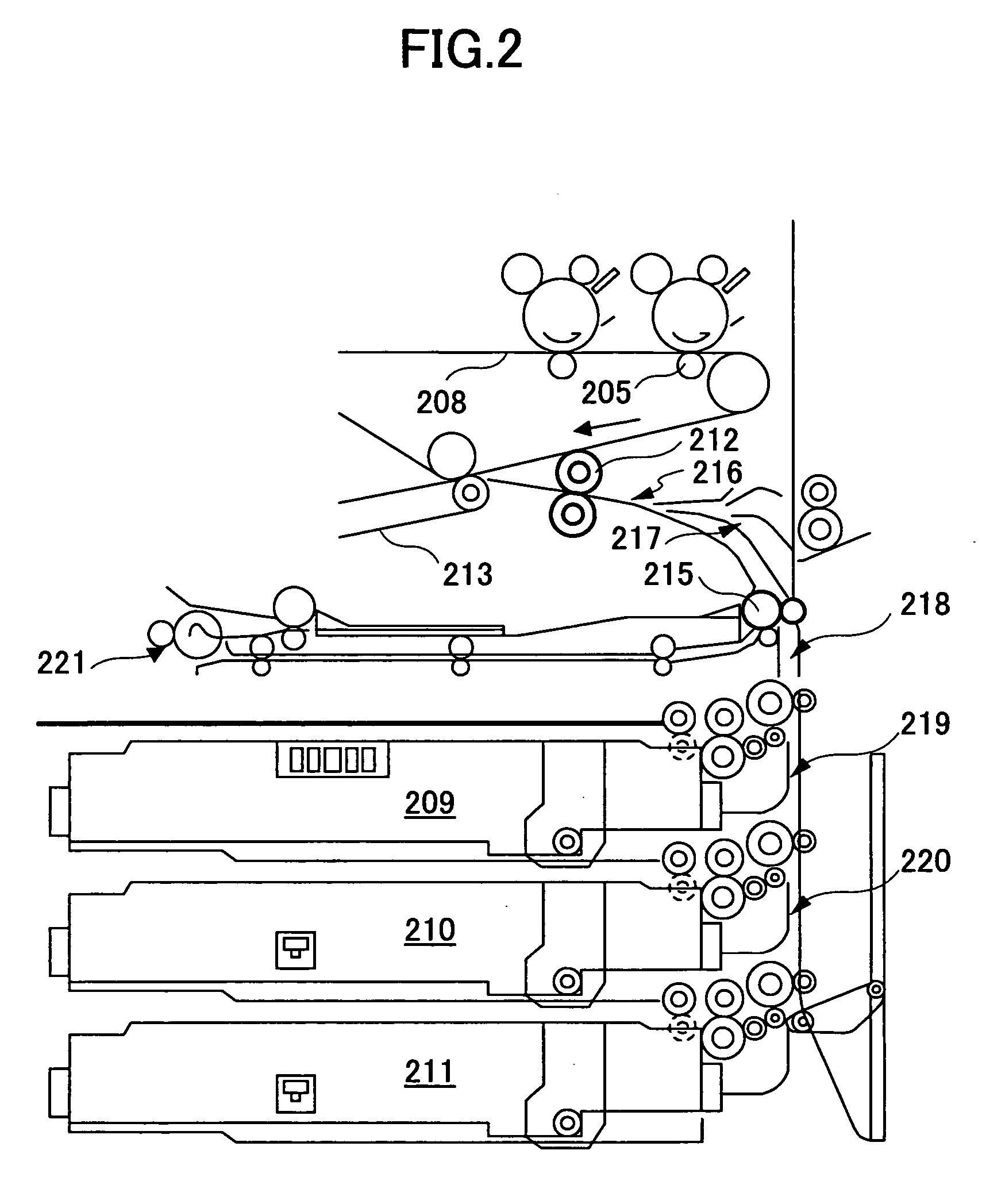
[0040] The printer 200 includes a transferring unit having an endless transferring belt 208. The transferring belt 280 is hung around three supporting rollers and is tensioned by a tension roller so as to be rotated clockwise as shown in FIG. 1. A transferring belt cleaning unit 207 is provided in the vicinity of the t...


PUM


Abstract

A sheet transferring device includes a feeding roller configured to feed a sheet; a transferring roller configured to transfer the sheet to the feeding roller; a sheet sensor configured to detect the sheet at a sheet transferring part from the transferring roller to the feeding roller; a measuring part configured to measure an interval of a rear end of a prior sheet and a head end of a following sheet based on a sheet detection signal of the sheet sensor; and a transferring control part configured to adjust a sheet transferring speed of the transferring roller so that the interval between the prior sheet and the following sheet is adjusted to a set value as corresponding to the interval measured by the measuring unit.

Description

BACKGROUND OF THE INVENTION [0001] 1. Field of the Invention [0002] The present invention generally relates to sheet transferring devices and image forming devices, and more specifically, to a sheet transferring device whereby plural sheets are transferred at a constant pitch in sequence, the sheet transferring device being used for a printer, copier, facsimile, or the like, and an image forming device having the sheet transferring device. [0003] 2. Description of the Related Art [0004] A printer, copier, facsimile, or the like is used as an image forming device wherein a sheet is transferred to an image forming position and an image is formed on the sheet. In such an image forming device, if an image forming operation of an imaging system and operation of a sheet transferring device sending the sheet to the image forming position are not coordinated, an image offset is generated on the sheet. In continuous printing or continuous copying wherein plural sheets are continuously sent i...

Claims


Application Information

Patent Timeline
IPC IPC(8): G03G15/00
CPCG03G2215/00721G03G2215/00945G03G15/6567G03G15/6564G03G15/235
Inventor ISOZAKI, TOSHIHIRO
Owner RICOH KK
Learn More