

Electrical connector
- Summary
- Abstract
- Description
- Claims
- Application Information
AI Technical Summary
Benefits of technology
Problems solved by technology
Method used
Image

Examples
Embodiment Construction
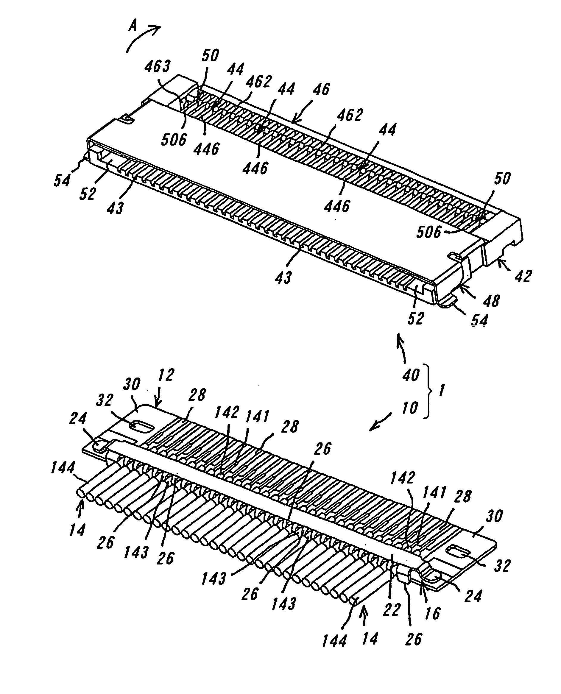
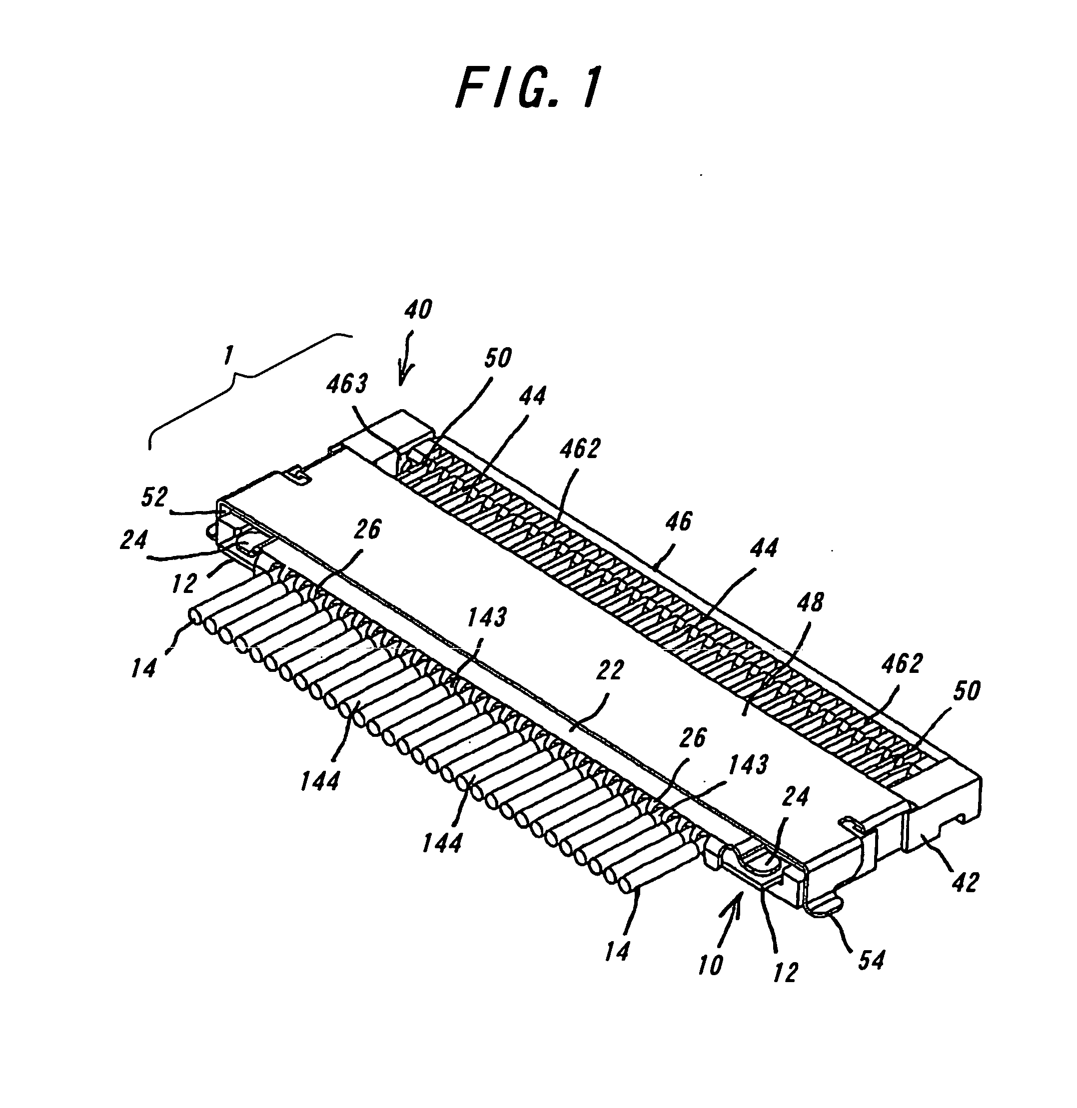
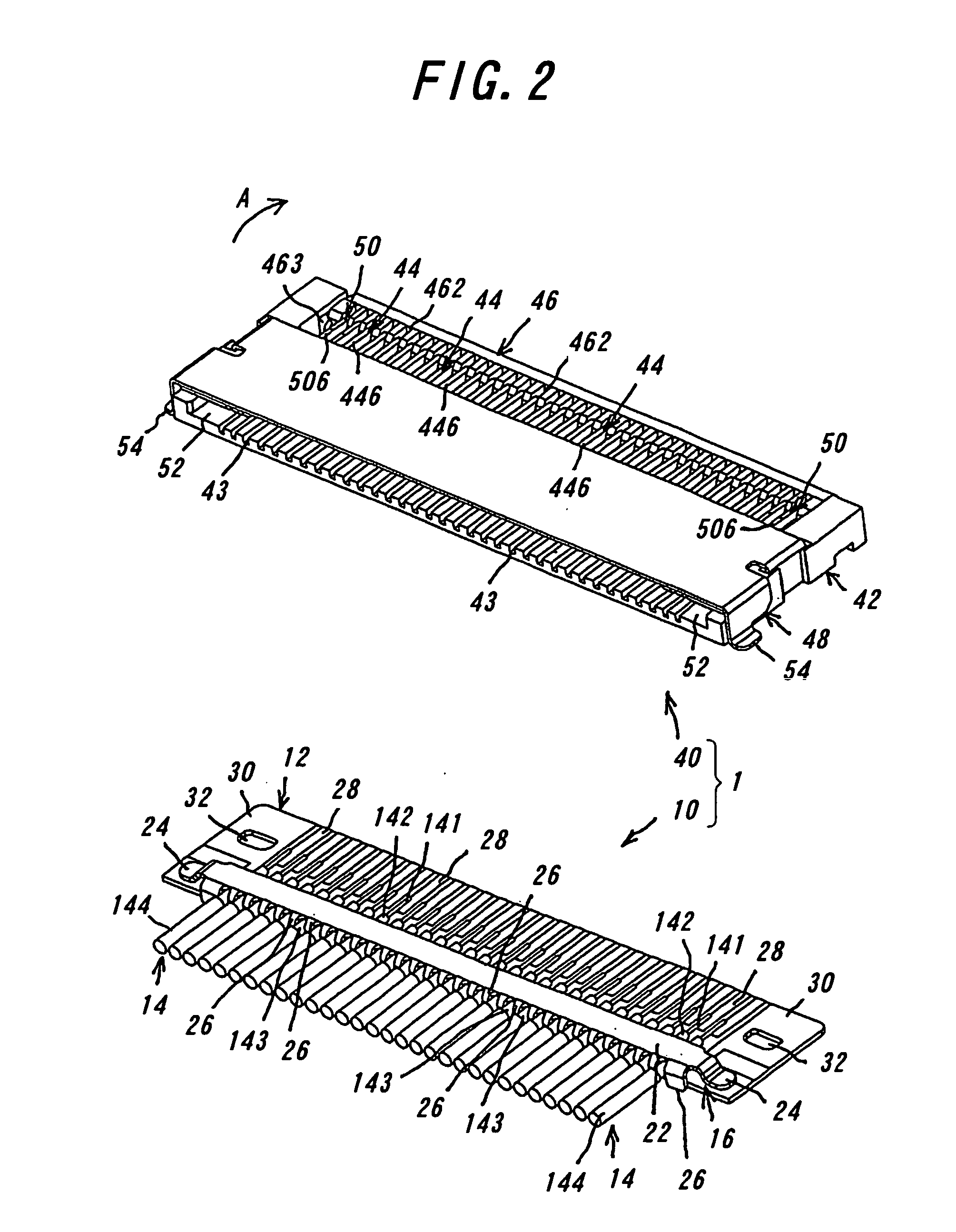
[0114] An electrical connector according to one embodiment of the invention will be explained with reference to the drawings. The electrical connector 1 comprises a plug connector 10 and a receptacle connector 40 which are to be detachably fitted with each other. FIG. 1 illustrates in a perspective view the plug connector and the receptacle connector according to the invention fitted with each other. FIG. 2 shows in a perspective view the plug connector and the receptacle connector according to the invention prior to the fitting with each other. FIG. 3 is a perspective view illustrating the plug connector in FIG. 2 being turned upside down. FIG. 4A is a perspective view illustrating the plug connector and contacts and locking members of the receptacle connector according to the invention, and FIG. 4B is a perspective view illustrating the contacts and locking members of the receptacle connector, which are in contact with the plug connector according to the invention. FIG. 5 illustra...
PUM
 Abstract
Description
Claims
Application Information