Eye implant and methods of positioning an artifical eye implant with the eye of a human or an animal

Inactive Publication Date: 2006-11-09
CARRIAZO CESAR C
View PDF2 Cites 1 Cited by
  • Summary
  • Abstract
  • Description
  • Claims
  • Application Information

AI Technical Summary

Benefits of technology

[0009] Therefore, the object of the invention is to provide an eye implant of the initially mentioned type, which overcomes the mentioned disadvantages of conventional eye implants, and especial

Problems solved by technology

However, concerning the restoration of the normal accommodation function of the lens with the possibility of focusing in the near and far range without the need for correcting visual aids, the results of surgical interventions are still insufficient.
In this manner, the application of sutures can be omitted, which delay the restoration of the visual power and can result in formation of astigmatism.
However, the employment of these lens constructions did not produce satisfying results, since the formation of a capsule bag fibrosis restricts the positional change of the intraocular lens (IOL).
In the attempt to replace the human eye lens by artificial lenses of comparable size, up to now, the limiting factor is in the circumstance that large surgical cuts are required for this, whereas worldwide the opposite tendency of performing very small cuts is to observe.
Also the a

Method used


Image

  • Eye implant and methods of positioning an artifical eye implant with the eye of a human or an animal
  • Eye implant and methods of positioning an artifical eye implant with the eye of a human or an animal
  • Eye implant and methods of positioning an artifical eye implant with the eye of a human or an animal

Examples


first embodiment

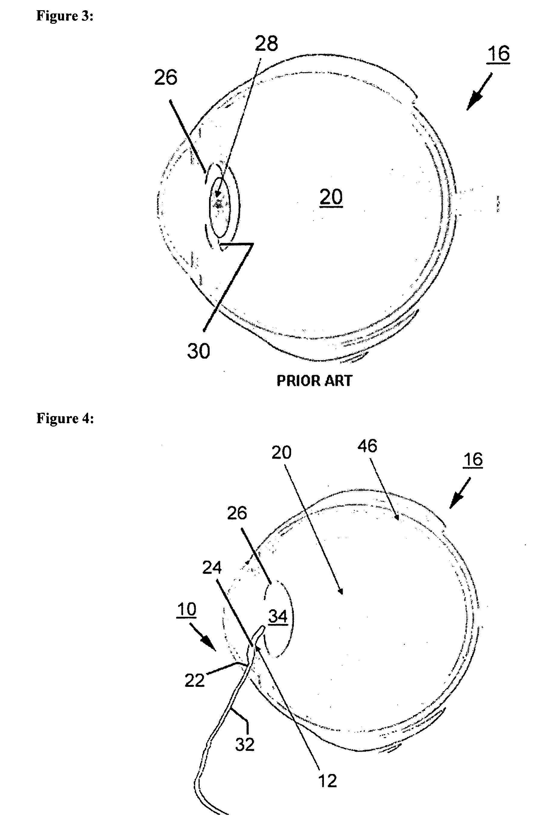
[0040]FIG. 4 shows a schematic representation of an artificial eye implant 10 according to the invention. Therein, the representation shows the eye implant 10 during introduction into the human eye 16. Therein, the introduction is effected through a small cut already used for removing the eye lens 18. One recognizes that the eye implant 10 shown in the illustrated embodiment serves as a substitute for the eye lens and includes a hollow body 12. Therein, the hollow body 12 is made of a biocompatible, flexible and extensible material and is able to be filled with a medium 14. As the materials for the artificial eye implant, especially biocompatible, flexible and extensible plastics, silicones and a plurality of other polymer compounds are considered, which have the requested properties. Silicone gum, acrylate, polyurethane, latex and polymethylmethacrylate (PMMA) are to be mentioned exemplarily.

[0041] Further, one recognizes that the eye implant 10 has a valve device 22 for filling th...

second embodiment

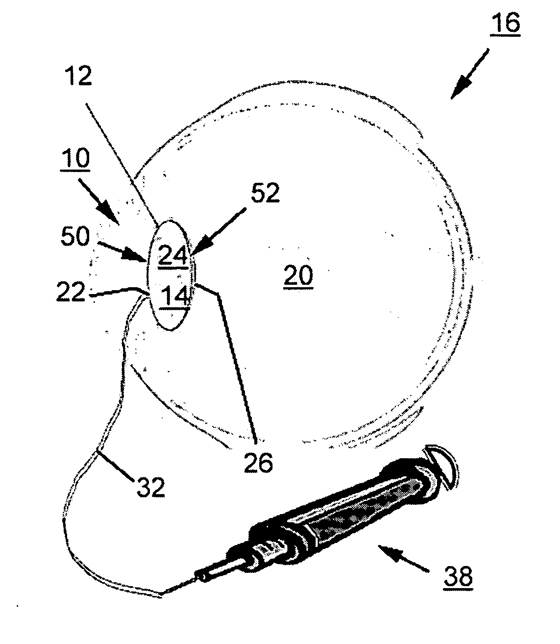
[0044]FIG. 8 shows a schematic representation of the eye implant 10 in a state filled with medium. One recognizes that instead of the tube connection 32, the medium 14 is now filled by means of a cannula 40 of a syringe-like filling device 38. Therein, the cannula 40 penetrates the valve device 22 of the hollow body 12 and thus places the medium 14 in the cavity 24 of the hollow body 12. After completely filling the cavity 24, the filling device 38 is retracted and the valve device 22 closes the hollow body 12. One recognizes that the eye implant 10 again has a curved front wall 50 and a curved back wall 52 facing the vitreous body 20 in the completely filled state.

third embodiment

[0045]FIG. 9 shows a schematic representation of an eye implant 10 during introduction into a posterior orbit 44 of the human eye 16. The vitreous body 20 has been removed from the posterior orbit 44. The eye implant 10 consisting of the hollow boy 12 with the cavity 24 is introduced into the posterior orbit 44 through a small cut, through which the vitreous body 20 has already been removed. Subsequently, the medium 14 is filled into the cavity 24 of the hollow body 12 through the valve device 22, the tube connection 32 detachably connected thereto, and the filling device 38 connected to the tube connection 32 (compare FIG. 10).

[0046] In state completely filled with the medium 14, illustrated in FIG. 11, the hollow body 12 approximately models the shape of the vitreous body 20 of the human or animal eye 16 and abuts the retina 46. After completely filling the hollow body 12, the tube connection 32 is detached from the eye implant 10 or the valve device 22 thereof, respectively.


PUM


Abstract

The invention relates to an artificial eye implant, especially as a substitute for an eye lens or a vitreous body of a human or animal eye consisting of a hollow body, wherein the hollow body is made of a biocompatible, flexible and extensible material and is able to be filled with a medium. The present invention further relates to methods of positioning an artificial eye implant within the eye of a human or an animal generally comprising the steps of: preparing an eye to receive an intraocular artificial eye implant wherein said implant consists of a hollow body made of a biocompatible, flexible and extensible material, said hollow body is able to be filled with a medium; inserting said intraocular eye implant into said eye via a small cut in said eye; positioning said implant in the non-filled state in the capsule bag or the posterior orbit of the eye; filling said implant with said medium; and closing the eye where said implant was inserted.

Description

CROSS-REFERENCE TO RELATED APPLICATIONS [0001] This application claims convention priority from European patent application no. 05 009 817.7, with a filing date of May 4, 2005. This application also claims the benefit of U.S. provisional patent application No. 60 / 677,737, with a filing date of May 4, 2005 The specifications and drawings of European patent application no. 05 009 817.7 and of U.S. provisional patent application No. 60 / 677,737 are specifically hereby incorporated herein by reference.BACKGROUND OF THE INVENTION [0002] The present invention relates to an artificial eye implant, especially as a substitute for an eye lens or a vitreous body of a human or animal eye consisting of a hollow body. The present invention further relates to methods of positioning an artificial eye implant within the eye of a human or an animal. [0003] Today, the clouding of the eye lens referred to as cataract is a very frequent disease, by which especially elder people are afflicted. The only po...

Claims


Application Information

Patent Timeline
IPC IPC(8): A61F2/16A61F9/013
CPCA61F2/14A61F9/0017A61F2/1613A61F2/16A61F9/007A61F2/141
Inventor CARRIAZO, CESAR C.
Owner CARRIAZO CESAR C
Why Eureka
Try Eureka