Mold-casting structure and improvement method for grounding of the same

US20060254042A1Inactive Publication Date: 2006-11-16MICROELECTRONICS TECH INC

Image

  • Mold-casting structure and improvement method for grounding of the same
  • Mold-casting structure and improvement method for grounding of the same
  • Mold-casting structure and improvement method for grounding of the same

Examples


Embodiment Construction

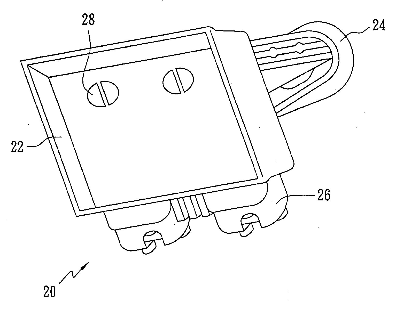
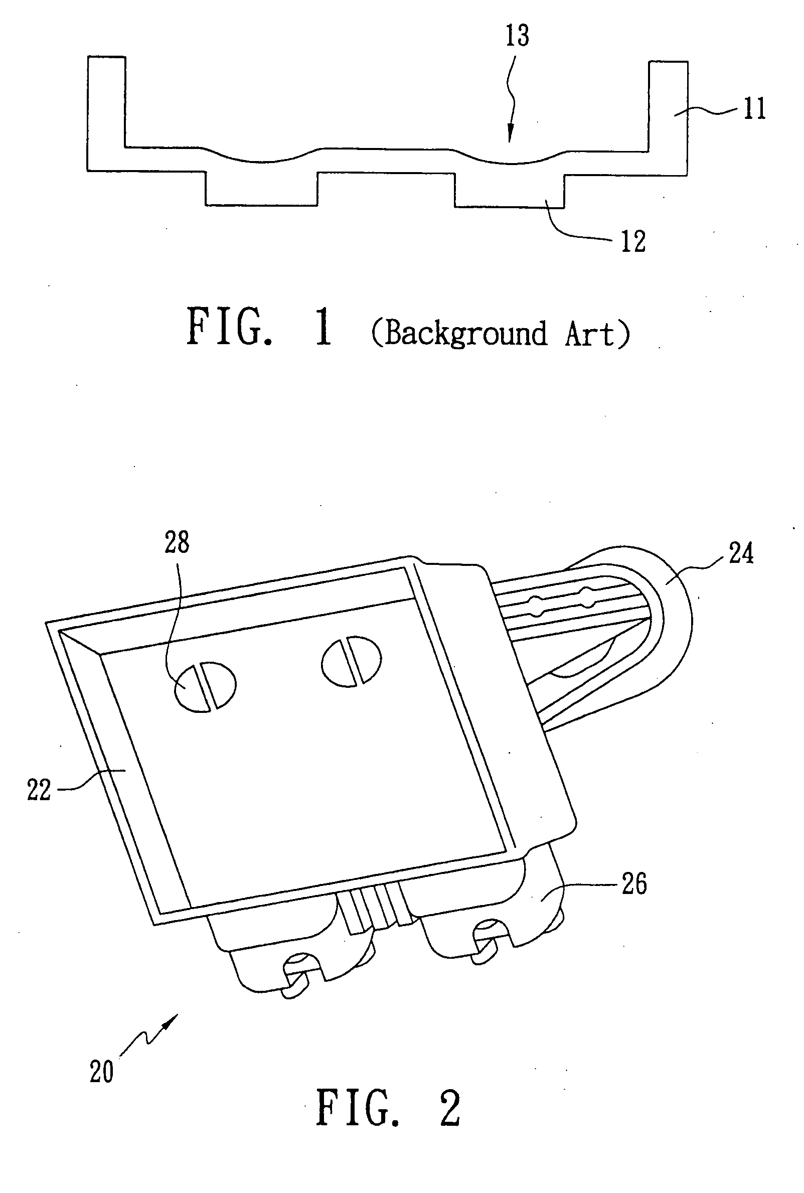
[0014] As shown in FIG. 2, an LNB structure 20 for microwave telecommunication comprises a housing 22, two horns 24, and two connector bases 26, where the housing 22, with the locations corresponding to the horns 24, is provided with two through holes shaped like semi-circles for the connection of signal cables to the horns 24. Only one horn 24 can be seen in FIG. 2, the other one is behind the housing 22 and thus not shown.

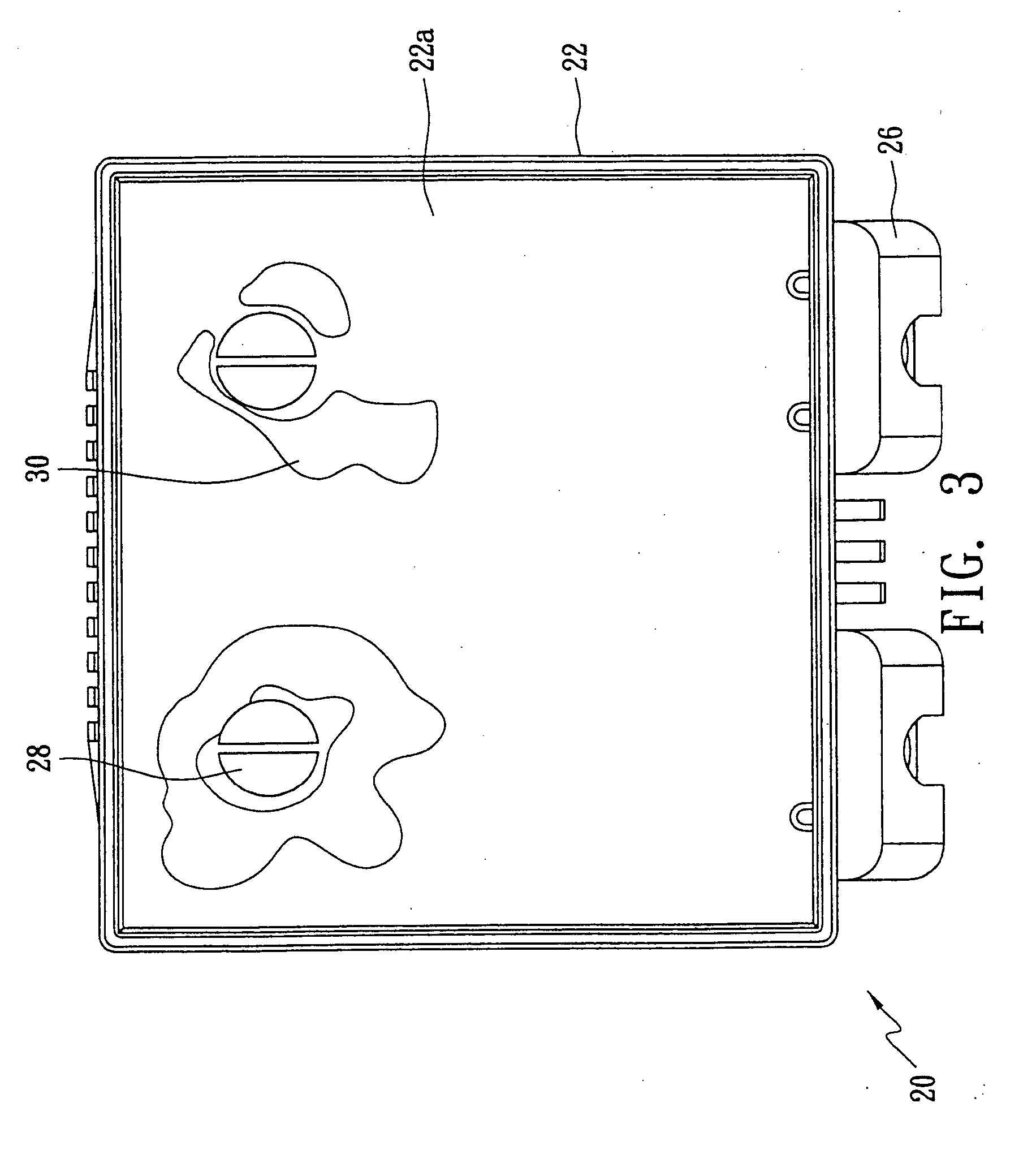
[0015]FIG. 3 illustrates the bottom view of the housing 22. After the LNB structure 20 is released from a mold and cooled down, a painting material such as a traditional paint, an ink marker or a red lead paint is daubed on the bottom surface 22a of the housing 22, and then scraped by a tool such as a scraper along a plane that is substantially equivalent to the bottom surface 22a but without protrusions or dishings. Accordingly, the paint on the protruded portions will be removed, so that the locations with remaining paint can be deemed dishings 30. In this emb...


PUM

PropertyMeasurementUnit
Diameteraaaaaaaaaa
Diameteraaaaaaaaaa
Distanceaaaaaaaaaa

Abstract

A mold-casting structure comprises at least one dishing and a plurality of micro-protrusions. The dishing(s) formed on the surface of a mold-casting body, the plurality of micro-protrusions sticking out of the surface of the dishing, and the tops of the micro-protrusions constitute on a plane, so that the grounding issue of the circuitry embedded in the mold-casting structure caused by the dishing can be resolved. The dishing can be verified by daubing paint and scrapping thereafter, the location of remaining paint is deemed the dishing. Moreover, a three-dimensional measurement instrument can be employed for more precise measurement. The micro-protrusions can be formed on the dishing by mechanical processing or electric discharge machining (EDM). Alternatively, a mold with a structure matching the micro-protrusions can be formed first, and consequently the micro-protrusions are formed directly by mold-filling, which is more suitable for mass production.

Description

BACKGROUND OF THE INVENTION [0001] (A) Field of the Invention The present invention is related to a mold-casting structure and the relevant electrical grounding method thereof. In view of the superior grounding efficiency of the mold-casting structure of the present invention, EMI (Electromagnetic Interference) can be prevented effectively. [0002] (B) Description of Related Art [0003] The satellite television systems employ a dish antenna to collect satellite signals, and the signals are then reflected to low noise block down converters (LNB) equipped at the focus of the dish antenna for amplifying the signals and reducing its frequency down to around 1 GHz, i.e., the radio signals are transformed to an intermediate frequency. The adjusted signals are transmitted to an indoor television channel selector via a cable to select the signals of a desired channel, and the selected signals are then amplified, modulated, and then converted into video and audio signals for television viewing...

Claims


Application Information

Patent Timeline
16 Nov 2006
Publication
US20060254042A1
IPC
B21B1/46; B22D27/00
CPC
B22D17/22; Y10T29/49995; Y10T29/4998
Inventors
CHOU, WEN PIN; YANG, LAN CHUN