Laser produced plasma EUV light source with pre-pulse

a plasma euv light source and laser technology, applied in the field of extreme ultraviolet (“ euv”) light sources, can solve the problems of large variation in the size of droplets, poor control of the positional stability of droplets, and stream which subsequently breaks into droplets rather chaotically

Inactive Publication Date: 2006-11-16
CYMER INC
View PDF7 Cites 164 Cited by
  • Summary
  • Abstract
  • Description
  • Claims
  • Application Information

AI Technical Summary

Problems solved by technology

However, this type of non-modulated jet, typically generates a stream which subsequently breaks into droplets rather chaotically.
The result is generally a large variation in droplet size and poor control over the positional stability of droplets both along the droplet path and in a plane normal to the path of the droplets.
For this scheme, even small misalignments may lead to non-effective coupling between the droplet and laser pulse resulting in reduced EUV output and a relatively low conversion efficiency between the input power and the output EUV power.
Moreover, with only a small difference between the melting point of the target material and the maximum operating temperature of the PZT, clogging or partial clogging of the nozzle may occur due to source material freezing on the surface of the capillary tube.
On the other hand, use of a PZT may also contribute to nozzle clogging due to the ultrasonic waves that are created when the PZT operates.
This cleaning, in turn, may wash out residual chunks that can clog the small nozzle orifice.
Thus, the use of electro-actuatable elements to modulate droplet formation tend to increase system complexity, may cause nozzle clogging and / or the use of electro-actuatable elements may be limited to certain source materials.
In addition to generating EUV radiation, these plasma processes also typically generate undesirable by-products in the plasma chamber (e.g. debris) which can potentially damage or reduce the operational efficiency of the various plasma chamber optical elements.
However, one disadvantage of using a CO2 laser in certain applications is the inability to focus 10.6 μm radiation tightly.
Unfortunately, both of these improvements have disadvantages.
This, in turn, may reduce EUV collection angle and necessitate complex schemes for protecting the laser input window from debris.
In some cases, these optical apparatus, due to their construction, may place a limit on the volume in which light generated by the EUV light source is usable by the apparatus.

Method used


Image

  • Laser produced plasma EUV light source with pre-pulse
  • Laser produced plasma EUV light source with pre-pulse
  • Laser produced plasma EUV light source with pre-pulse

Examples


Embodiment Construction

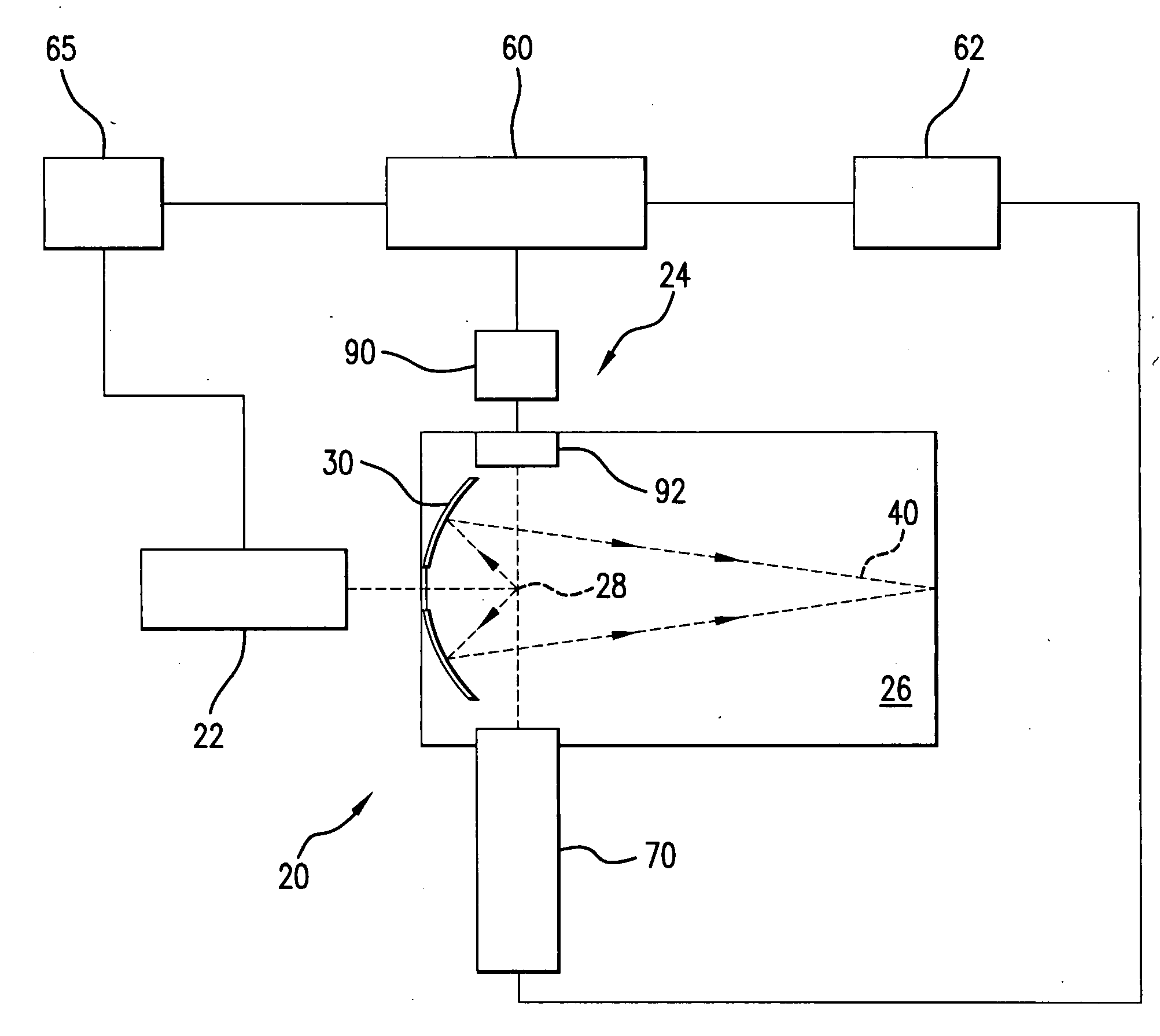
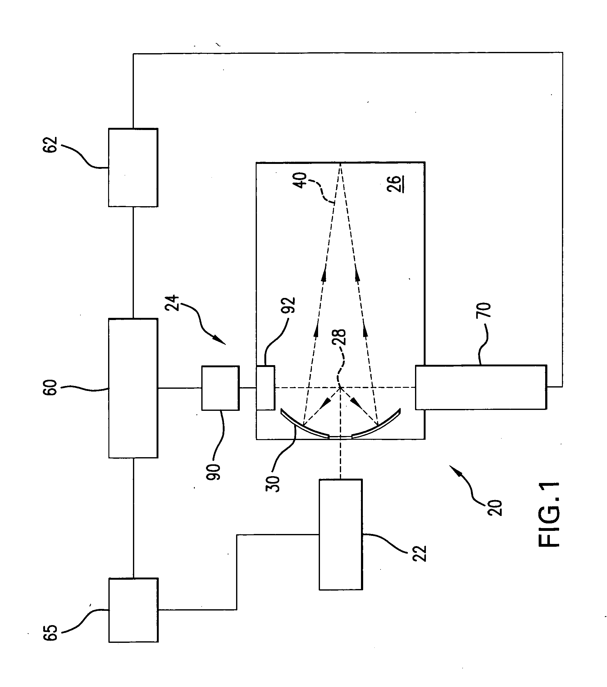
[0027] With initial reference to FIG. 1 there is shown a schematic view of an exemplary EUV light source, e.g., a laser produced plasma EUV light source 20 according to an aspect of the present invention. As shown in FIG. 1, and described in further detail below, the LPP light source 20 may include a source 22 for generating light pulses and delivering the light pulses into a chamber 26. As detailed below, the light pulses may travel along one or more beam paths from the source 22 and into the chamber 26 to illuminate one or more target volumes.

[0028] As further shown in FIG. 1, the light source 20 may also include a source material delivery system 24, e.g., delivering droplets of a source material into the interior of a chamber 26 to a target volume 28 where the source material targets will be irradiated by one or more light pulses, e.g. a pre-pulse and thereafter a main pulse, to produce a plasma and generate an EUV emission. The source material may include, but is not limited to...


PUM


Abstract

A method for generating EUV light is disclosed which may include the acts/steps of providing a source material; generating a plurality of source material droplets; simultaneously irradiating a plurality of source material droplets with a first light pulse to create irradiated source material; and thereafter exposing the irradiated source material to a second light pulse to generate EUV light, e.g. by generating a plasma of the source material. In another aspect, an EUV light source may include a droplet generator delivering a plurality of source material droplets to a target volume; a source of a first light pulse for simultaneously irradiating a plurality of droplets in the target volume to produce an irradiated source material; and a source of a second light pulse for exposing the irradiated source material to generate EUV light. The droplet generator may comprise a non-modulating droplet generator and may comprise a multi-orifice nozzle.

Description

[0001] The present application is a continuation-in-part application of co-pending U.S. patent application Ser. No. 11 / 067,124 filed on Feb. 25, 2005, entitled METHOD AND APPARATUS FOR EUV PLASMA SOURCE TARGET DELIVERY, attorney docket number 2004-0008-01, the entire contents of which are hereby incorporated by reference herein. [0002] The present application is also a continuation-in-part application of co-pending U.S. patent application Ser. No. 11 / 174,443 filed on Jun. 29, 2005, entitled LPP EUV PLASMA SOURCE MATERIAL TARGET DELIVERY SYSTEM, attorney docket number 2005-0003-01, the entire contents of which are hereby incorporated by reference herein. [0003] The present application is also related to co-pending U.S. nonprovisional patent application entitled SOURCE MATERIAL DISPENSER FOR EUV LIGHT SOURCE filed concurrently herewith, attorney docket number 2005-0102-01, the entire contents of which are hereby incorporated by reference herein. [0004] The present application is also ...

Claims


Application Information

Patent Timeline
Patent Type & Authority Applications(United States)
IPC IPC(8): G01J3/10
CPCH05G2/003H05G2/005H05G2/008
Inventor BYKANOV, ALEXANDER N.KHODYKIN, OLEH
Owner CYMER INC
Why Eureka
Try Eureka