Handheld scanning subsurface detector

Inactive Publication Date: 2006-11-16
HILTI AG
View PDF7 Cites 6 Cited by
  • Summary
  • Abstract
  • Description
  • Claims
  • Application Information

AI Technical Summary

Benefits of technology

[0013] The shielding means advantageously comprises at least one or more layers of an electrically conductive material, so that a sufficient shielding from electromagnetic radiation in the high-frequency range can be achieved in an economical manner based on the skin effect. Highly permeable materials (ferrite, plastoferrite) and/or highly dielectric materials (barium titanate) are also well suited for shielding because of the hysteres

Problems solved by technology

However, due to the air gap between the guide wheels that is present when scanning in the space between the sensor device and the wall surface, interfer

Method used


Image

  • Handheld scanning subsurface detector
  • Handheld scanning subsurface detector
  • Handheld scanning subsurface detector

Examples


Example

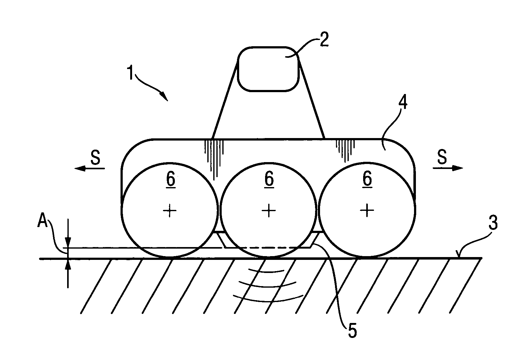
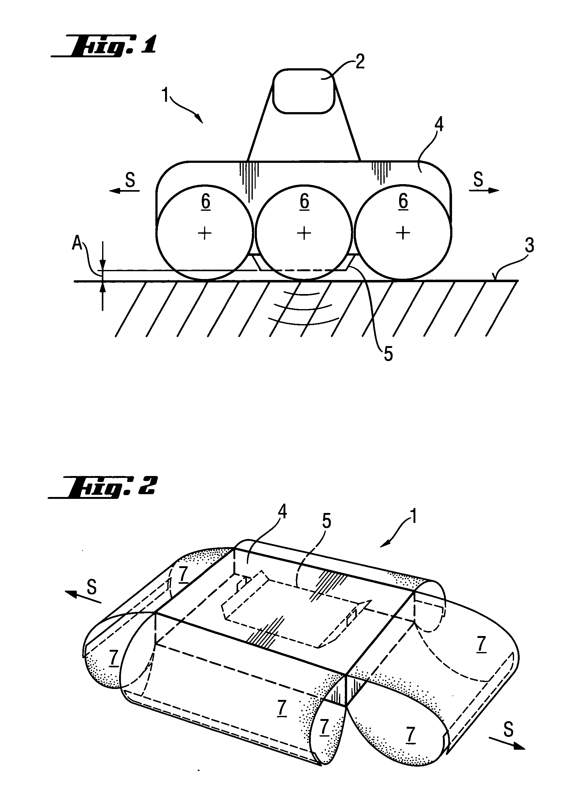
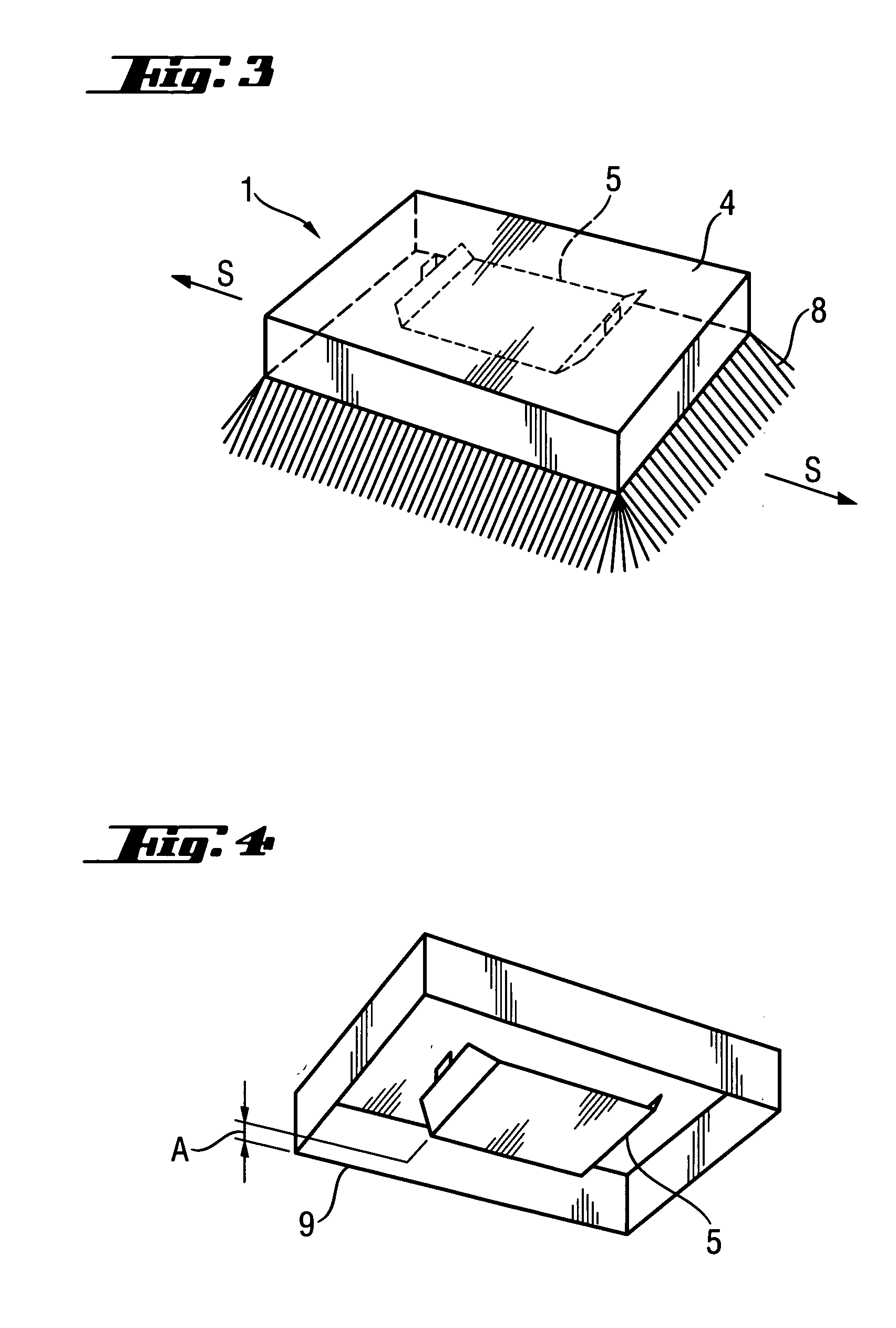
[0026] According to FIG. 1, a handheld subsurface detector 1 which scans along a scanning direction S has a housing 4 which can be held by a handle 2 and which is formed for being guided in a predetermined manner at an intervening distance (A) from the wall along a wall surface 3 to be examined. In addition, the subsurface detector 1 has a sensor device 5 which is oriented toward the wall side and which is formed as a planar antenna 1 for the electromagnetic high-frequency range from 100 MHz to 10 GHz. Shielding means is arranged on each longitudinal side of the housing 4 (the side oriented longitudinal to the scanning direction S) for shielding against electromagnetic radiation. The shielding means is formed as three full-surface, radially large guide wheels 6 which are arranged closely adjacent to one another and which are formed of conductive, magnetic plastic material that absorbs electromagnetic radiation and comprises carbon particles and ferrite grains. These shielding means ...


PUM


Abstract

A handheld scanning subsurface detector (1) has a handheld housing (4) which is designed to be guided at a predetermined distance over a wall surface (3) to be examined within a distance (A) from the wall, a sensor device (5) which is sensitive in the electromagnetic high-frequency range, and electromagnetically active shielding elements which shield the intervening distance (A) from the wall from the electromagnetic stray radiation in the high-frequency range, at least within a large circumferential area of a shielding contour (9) that surrounds the sensor device (5) externally.

Description

BACKGROUND OF THE INVENTION [0001] 1. Field of the Invention [0002] The present invention relates to a handheld scanning subsurface detector, particularly for detecting reinforcements or lines embedded in concrete or masonry. [0003] 2. Description of the Prior Art [0004] The detection of embedded objects plays an important role in the constructional industry for detecting iron reinforcements, metal pipes, electric lines, or plastic conduits. The detection measurement methods upon which the subsurface detection is based are not the subject matter of the present application and will not be discussed in detail. Generally, embedded objects are detected and identified by changes in the impedance of an impressed magnetic near-field, e.g., according to U.S. Pat. No. 6,541,965, by changes in the impedance of an impressed electric near field according to WO 02063343, or electromagnetically by radar according to U.S. Pat. No. 5,541,605. [0005] Wall surfaces which are coarse and rough (with fl...

Claims


Application Information

Patent Timeline
IPC IPC(8): G01R19/00
CPCG01V3/15
Inventor WUERSCH, CHRISTOPHKANEIDER, WILFRIED
Owner HILTI AG
Why Eureka
Try Eureka