Eureka AIR delivers breakthrough ideas for toughest innovation challenges, trusted by R&D personnel around the world.

Integral three-dimensional imaging with digital reconstruction

a three-dimensional image and digital reconstruction technology, applied in the field of integrated three-dimensional image and digital or optical reconstruction, can solve the problems of resolution, dynamic range, and adverse effects on the overall quality of the reconstructed image obtained by optical integral imaging, so as to enhance the reconstructed image and improve the quality of the imag

Inactive Publication Date: 2006-11-16
UNIV OF CONNECTICUT
View PDF26 Cites 16 Cited by
  • Summary
  • Abstract
  • Description
  • Claims
  • Application Information

AI Technical Summary

Benefits of technology

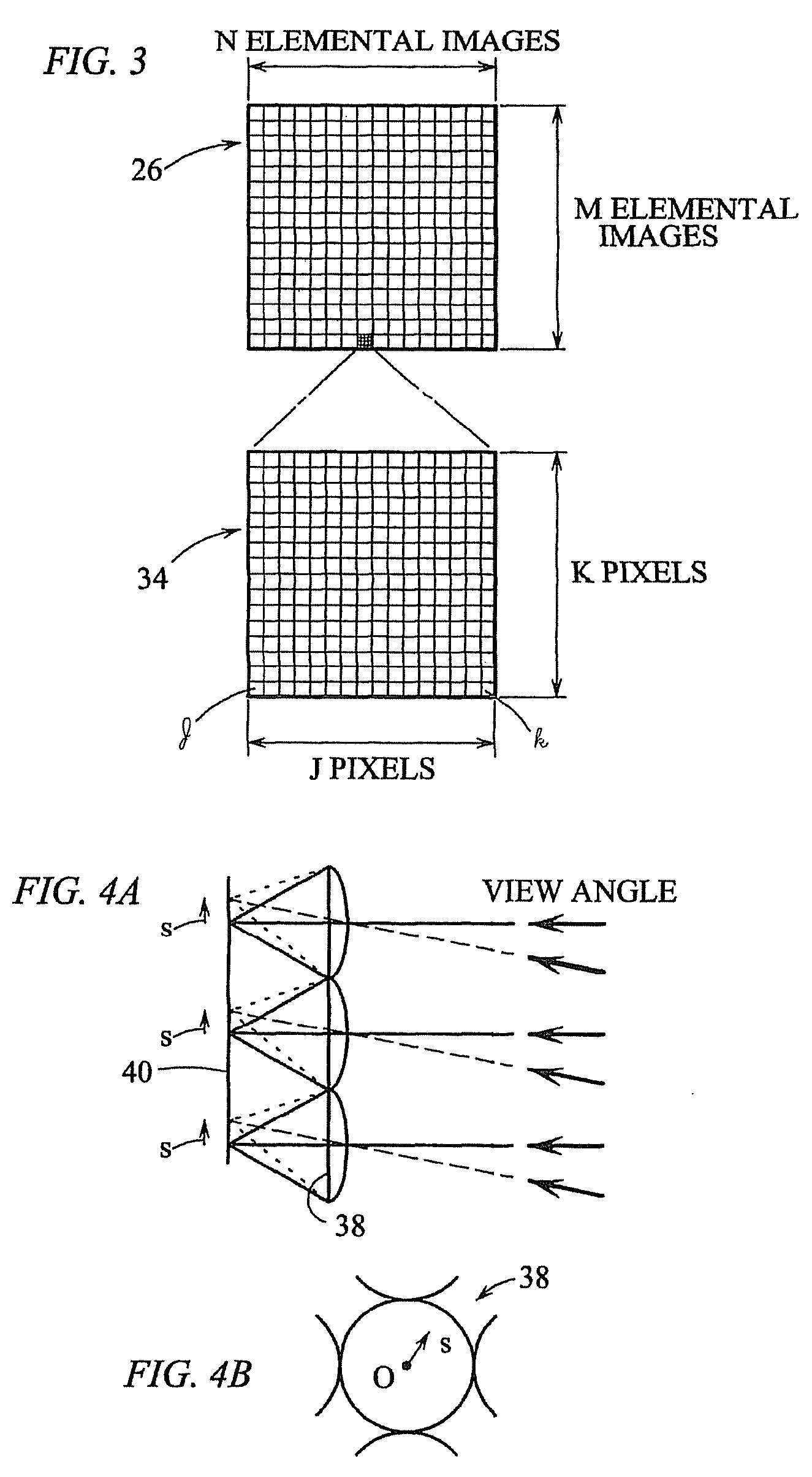
[0006] A computer-based three-dimensional image reconstruction method and system are presented in the present invention. The three-dimensional image reconstruction by digital methods of the present invention can remedy many of the aforementioned problems. Moreover, digital computers have been used for imaging applications and recent developments in computers allow for the application of digital methods in almost real-time. In accordance with the present invention, an elemental image array of a three-dimensional object is formed by a micro-lens array, and recorded by a CCD camera. Three-dimensional images are reconstructed by extracting pixels periodically from the elemental image array using a computer. Images viewed from an arbitrary angle can be retrieved by shifting which pixels are to be extracted. By reconstructing the three-dimensional image numerically with a computer, the quality of the image can be improved, and a wide variety of digital image processing can be applied. The present invention can be advantageously applied in applications for optical measurement and remote sensing. Image processing methods can be used to enhance the reconstructed image. Further, the digitally reconstructed images can be sent via a network, such as a local area network (LAN), a wide area network (WAN), an intranet, or the Internet (e.g., by e-mail or world wide web (www)).

Problems solved by technology

This optical reconstruction may introduce a resolution limitation in three-dimensional integral imaging, such is described in H. Hoshino, F. Okano, H. Isono, and I. Yuyama, “An Analysis Of Resolution Limitation Of Integral Photography,” J. Opt. Soc. Am.
In this way, due to the limitation of optical devices such as liquid crystal displays (LCD), the resolution, the dynamic range, and the overall quality of the reconstructed image obtained by optical integral imaging are adversely affected.

Method used


Image

  • Integral three-dimensional imaging with digital reconstruction
  • Integral three-dimensional imaging with digital reconstruction
  • Integral three-dimensional imaging with digital reconstruction

Examples


Embodiment Construction

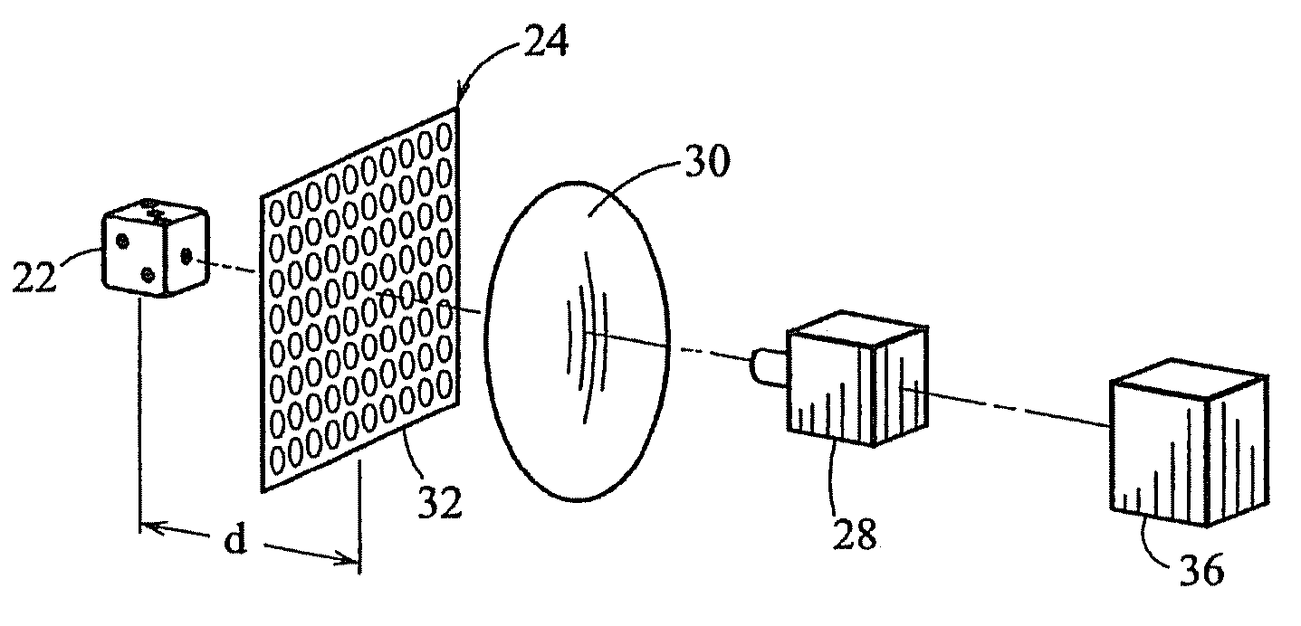
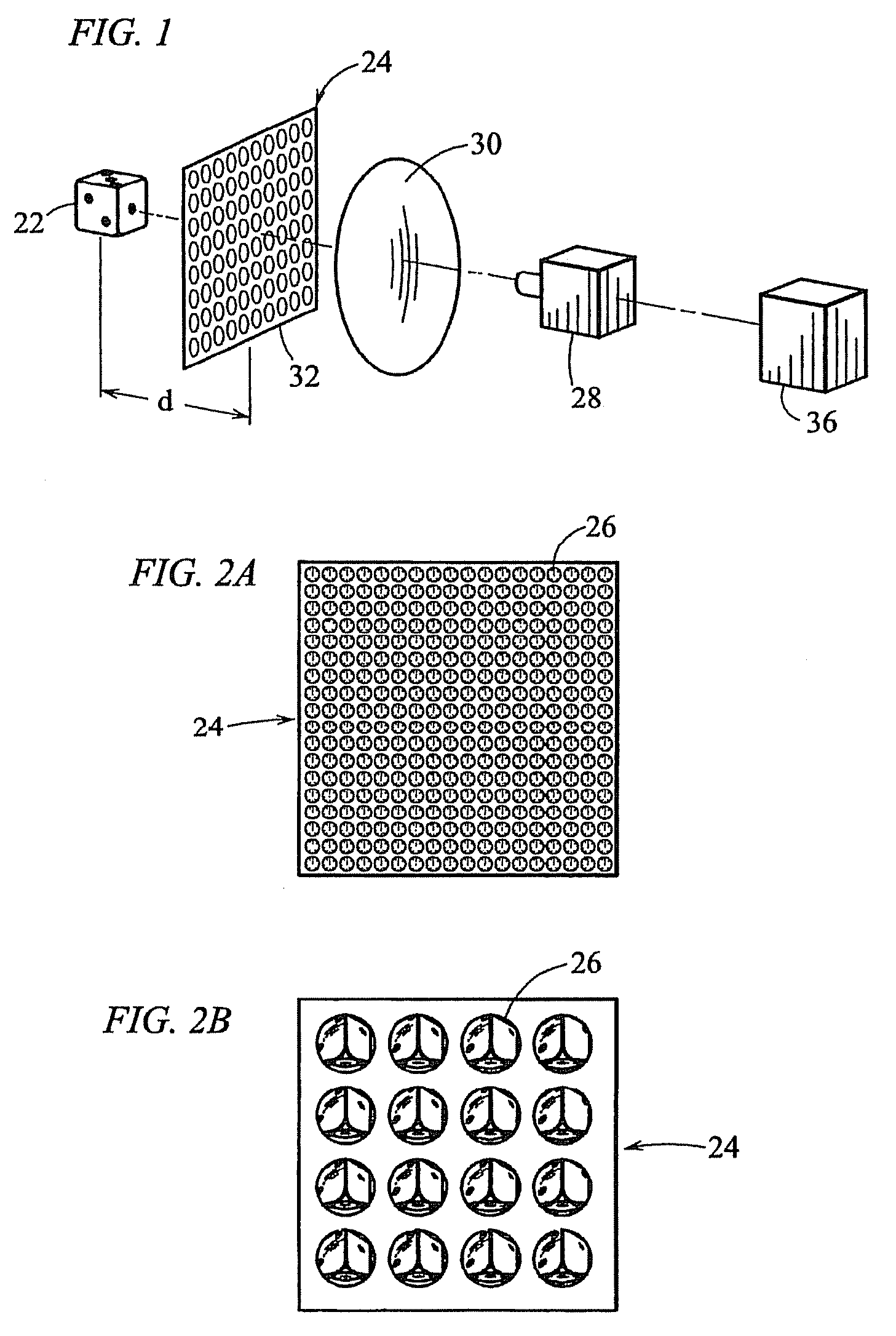
[0023] Referring to FIG. 1, a system for obtaining image arrays is generally shown at 20. A three-dimensional object (e.g., a die) 22 is illuminated by light (e.g., spatially incoherent white light). A micro-lens array 24 is placed in proximity to the object 22 to form an elemental image array 26 (FIGS. 2A and B) which is focused onto a detector 28, such as a CCD (charge coupled device) camera by a lens 30. The micro-lens array 24 comprises an N×M array of lenses 32 such as circular refractive lenses. In the present example, this N×M array comprises a 60×60 array of micro-lenses 32 in an area of 25 mm square. The magnification factor of the elemental image array formed by the camera lens 30 is adjusted such that the size of the elemental image array becomes substantially the same as the size of the imaging area of the CCD camera 28. In the present example, the distance between the object 22 and the micro-lens array 24 is 50 mm. Also, in this example, the camera lens 30 has a focal l...


PUM


Abstract

An elemental image array of a three-dimensional object is formed by a micro-lens array, and recorded by a CCD camera. A display device may be connected directly or indirectly to the computer to display the image of the three-dimensional object.

Description

CROSS-REFERENCE TO RELATED APPLICATIONS [0001] This is a divisional of application Ser. No. 10 / 056,497 filed Jan. 23, 2002, which application claims the benefit of U.S. Provisional Application No. 60 / 263,444, filed on Jan. 23, 2001, priority to both of which is claimed herein and both of which are incorporated herein by reference as if set forth at length.TECHNICAL FIELD [0002] This disclosure relates to integral imaging of three-dimensional objects and the digital or optical reconstruction thereof. BACKGROUND OF THE INVENTION [0003] Three-dimensional image reconstruction by coherence imaging or video systems provides useful information such as the shape or distance of three-dimensional objects. Three-dimensional image reconstruction by coherence imaging is further described in J. Rosen and A. Yariv, “Three-dimensional Imaging of Random Radiation Sources,” Opt. Lett. 21, 1011-1013 (1996); H. Arimoto, K. Yoshimori, and K. Itoh, “Retrieval of the Cross-Spectral Density Propagating In ...

Claims


Application Information

Patent Timeline
IPC IPC(8): G02B27/22
CPCH04N13/0445G02B27/2214G03B35/24H04N13/0406H04N13/0059H04N13/0232H04N13/0003H04N13/10H04N13/194H04N13/232H04N13/307H04N13/349G02B30/27
Inventor JAVIDI, BAHRAM
Owner UNIV OF CONNECTICUT
Why Eureka
Eureka Blog
Learn More