Coated printing sheet and process for making same

a printing sheet and coating technology, applied in the field of printing sheets, can solve the problems of bulky paper, inherent conflict between the calendering necessary, uneven surface, etc., and achieve the effect of effective transport, high dispersibility, and effective adjustment of ink setting behaviour

Inactive Publication Date: 2006-11-16
SAPPI NETHERLANDS SERVICES
View PDF11 Cites 28 Cited by
  • Summary
  • Abstract
  • Description
  • Claims
  • Application Information

AI Technical Summary

Benefits of technology

[0015] To effectively adjust the ink setting behaviour of such an image receptive coating, the polarity of this internal porous surface must be controlled. The ink setting is to be adjusted such as to allow the freshly printed sheet to be almost immediately further processed or printed on the other side (so called perfecting). For example it should be possible to print the second side after the usual time necessary for handling, i.e. after 10 to 15 minutes. Ink setting is quantified as ink set-off values for given times e.g. by using a Skinnex 800 analyzer. For fast ink setting, the surface of the image receptive coating layer is preferentially non-polar (high dispersive part of the surface energy), as then the overall non-polar offset ink oils are not repelled by the surface and are effectively transported into the pores assisted by capillary forces. The polarity of the surface can be adjusted by adding corresponding components to the coating composition, which components modify the hydrophobic character of the surface. Typically the ink setting can be adjusted to show an ink set-off of less than 0.3 at 30 secs, preferably of in the range of between 0.15 to 0.25 at 30 seconds. This is possible substantially without substantially modifying the porosity structure in the above-mentioned region of pores smaller than 200 nm. Fast ink-setting in combination with low sensitivity back trap mottle and ink refusal is realized by simultaneously creating a fine pore structure and making the surface more polar.
[0016] Examples of such components shall be given below. Advantageously, the polar part of the surface energy of the surface of the image receptive coating layer is less than 7 mN / m, preferably less than 6 mN / m as determined by contact angle measurements, at a Parker Print Surf (PPS) surface roughness of 0.8 to 1 μm, preferably of less than 0.9 μm. However, with the given porous structure, the polar part of the surface energy should preferentially also not be too low, such as to prevent the ink to be absorbed into the paper too quickly and too effectively by the capillary forces provided by the tubes. Correspondingly, the polar part of the surface energy should preferentially not be lower than 4 mN / m.

Problems solved by technology

The finishing effect achieved using a gloss calender, however, is not as smooth or as flat, and therefore not as glossy, as the surface produced using an apparatus capable of applying higher pressure.
There is therefore an inherent conflict between the calendering necessary for achieving a particular gloss and the bulk properties of the paper.
If, on the other hand, high gloss is achieved by applying high pressure in the calendering process, bulk is lost.
Calendering is not the only possibility to achieve gloss on the surface of a printing sheet.
If the ink setting is too fast, the tacky ink has the tendency to get absorbed into the paper too quickly leading e.g. to problems associated with lifting off surface parts of the paper during the printing process (breaking of the cohesion within the printing sheet, known in the field as picking), mottling or too low printing gloss values.
On the other hand, if the ink setting is too slow, too much time has to be allowed for drying of the ink and correspondingly the printing speed has to be reduced.

Method used


Image

  • Coated printing sheet and process for making same
  • Coated printing sheet and process for making same
  • Coated printing sheet and process for making same

Examples


Embodiment Construction

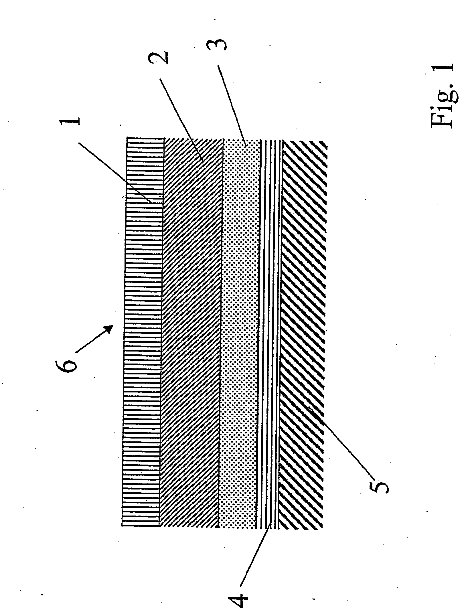
[0044] Referring to the drawings, which are for the purpose of illustrating the present preferred embodiments of the invention and not for the purpose of limiting the same, FIG. 1 shows a cut through a paper representing a first example of a printing sheet according to the present invention. The printing sheet comprises a substrate 5, of which only the top part is displayed in FIG. 1. As a first layer on this substrate 5 there is a possibly pigmented sizing layer 4, then follows a third layer 3, a second layer 2 and a top layer 1. FIG. 1 only displays one of the lateral surfaces of the printing sheet, if the printing sheet is coated on both sides, which is usually the case, the structure displayed in FIG. 1 is also present on the bottom part of the printing sheet, the sequence of the layers being a mirror image of the sequence displayed in FIG. 1.

[0045] In the following, each of the layers as well as their components shall be described in more detail, the method for manufacturing t...


PUM

PropertyMeasurementUnit
pore widthsaaaaaaaaaa
surface energyaaaaaaaaaa
surface roughnessaaaaaaaaaa

Abstract

A printing sheet is described comprising a substrate and, on at least one side of the substrate, an image receptive coating layer with a cumulative porosity volume of pore widths below 200 nm as measured using nitrogen intrusion methods of more than 0.006 cm3 per gram paper. In particular in the context of printing sheets with high-gloss this particular porosity distribution leads to a quick and easily adjustable ink setting behaviour. Additionally a method for manufacturing such a printing sheet is described using organic, i.e. polymer and inorganic particulate pigments of fine particle characteristics.

Description

TECHNICAL FIELD [0001] The present invention relates to a printing sheet comprising a substrate and, on at least one side of the substrate, an image receptive coating layer. It additionally relates to a method of manufacturing as well as to a use of such a printing sheet. BACKGROUND OF THE INVENTION [0002] In particular in the field of high-quality of offset printing e.g. in artistic reproductions and glossy journals etc., paper is needed which shows high gloss, is easily printable, has quick ink drying behaviour and at the same time has a high bulk and stiffness, i.e. which has a low density. [0003] In the manufacturing of such a paper, the finishing operation is usually a calendering process, in which a paper web is passed between the nips formed between one or more pairs of rolls and the surface of the web is thereby flattened to form a smooth and glossy surface. Simultaneously, the thickness of the paper web is reduced and the web is densified. Calendering generally increases th...

Claims


Application Information

Patent Timeline
Patent Type & Authority Applications(United States)
IPC IPC(8): B41M5/00B41M5/52D21H19/38D21H19/40D21H19/76D21H19/82D21H21/52
CPCB41M5/52B41M5/5218B41M5/5227B41M5/5236B41M5/5254D21H21/52D21H19/385D21H19/40D21H19/76D21H19/82B41M5/5281B41M5/00D21H19/38
Inventor HAENEN, J P
Owner SAPPI NETHERLANDS SERVICES
Why Eureka
Try Eureka