Fuel cell

a fuel cell and cell technology, applied in cell components, electrochemical generators, electrolytes, etc., can solve the problems of energy loss, complex configuration of the above-mentioned fuel cell system, temperature difference between an inlet and an outlet of the coolant, etc., to prevent excessive cooling at the inlet side, and reduce the risk of energy loss

Inactive Publication Date: 2006-11-16
TOYOTA JIDOSHA KK
View PDF2 Cites 31 Cited by
  • Summary
  • Abstract
  • Description
  • Claims
  • Application Information

AI Technical Summary

Benefits of technology

[0057] In the present invention, as described above, the low heat conducting section is provided at the inlet side of the coolant channel. Thus, heat transfer at the inlet side of the coolant is restricted, and excessive cooling at the inlet side is prevented, thereby making it possible to prevent the deviation of the temperature distributions in the coolant channel.
[0058] In addition, in the present invention, the electrolyte is made by laminating the hydrogen separating metal layer and the proton conductor layer, as described above. Thus, in the case where deviation occurs in temperature distribution, and then, the temperature is out of the range of an operating temperature, there is a danger that the hydrogen separating metal layer made of such as palladium or vanadium and the like deteriorates and battery performance is degraded. In addition, since an electrically conducting resistance of the proton conductor layer has temperature dependency and in general, the electrically conducting resistance of the proton conductor layer increases in a low temperature region. There is a danger that the deviation in the low temperature direction causes lowering of electric power generation efficiency. In the fuel cell according to the present invention, the low heat conducting section is formed at the inlet side of the coolant channel, and thus, the deviation in the temperature distributions hardly occurs, and deterioration of the hydrogen separating metal layer or lowering of the electric power generation efficiency can be prevented.
[0059] In addition, the hydrogen separating metal layer is permeated by hydrogen supplied to the anode channel or hydrogen from the hydrogen-containing gas supplied to the anode channel. Then, the hydrogen having permeated the hydrogen separating metal layer is established in a proton state, permeates the proton conductor layer, and reaches the cathode channel. In the cathode channel, the oxygen contained in the oxygen-containing gas supplied to the cathode channel and the hydrogen proton (called H+, hydrogen ion) are reacted with each other to generate water. In the fuel cell, for example, by forming the anode electrode and the cathode electrode are formed on the electrolyte, it possible to acquire electric energy between the anode electrode and the cathode electrode along with the water generation as described above.
[0060] As described above, according to the present invention, there can be provided a fuel cell capable of simplifying a configuration of the fuel cell system, capable of improving energy efficiency of the system, and capable of reducing the deviation in temperature distribution.

Problems solved by technology

As a result, in the conventional fuel cell system, there has been a problem that an energy loss occurs and a configuration of the above described fuel cell system becomes complicated.
However, when temperature control is carried out while supplying the coolant to the coolant channel, a temperature difference occurs between an inlet and an outlet of the coolant, and deviation is likely to occur in temperature distribution of the fuel cell.
Specifically, when the coolant is introduced to the coolant channel, a temperature difference between the coolant and its periphery is large at the inlet side of the coolant, and thus, excessive cooling is likely to occur.
At the outlet side, a temperature difference between the coolant and its periphery is small, and cooling is likely to be insufficient.
As a result, at the inlet side and outlet side of the coolant, deviation is likely to occur in temperature distribution of the fuel cell.
However, cooling means disclosed in patent documents 3 to 7 have had the problems described below, respectively.
Thus, it is actually very difficult to insert the tapered pipe described in patent document 3 into each channel.
In addition, a pipe having been inserted into a cooling gas inlet passage precludes the flow of a coolant, and thus, a pressure loss increases, and a loss of supply drive force of a fluid such as a cooling gas increases.
As a result, there occurs a problem that energy efficiency of a fuel cell system is lowered.
Therefore, there has been a problem that a manufacturing process becomes complicated.
In addition, in the fuel cell using such a catalyst, there has been a problem that the deviation of temperature distributions in the fuel cell cannot be sufficiently reduced.
In addition, in the fuel cell system of patent document 5 as well, there has been a problem that the deviation of temperature distributions in the fuel cell cannot be sufficiently reduced.
That is, in such a fuel cell system, there has been a danger that a temperature increases at an end of a cooling gas channel and a temperature decreases at a center of the channel.
In addition, in the cooling means described in patent document 6 and patent document 7 as well, the deviation of temperature distribution in the fuel cell cannot be sufficiently reduced.
Thus, a heat transfer promotion effect can be hardly attained, and the deviation of the temperature distributions has not been sufficiently eliminated successfully.

Method used


Image

  • Fuel cell
  • Fuel cell
  • Fuel cell

Examples


embodiments

First Embodiment

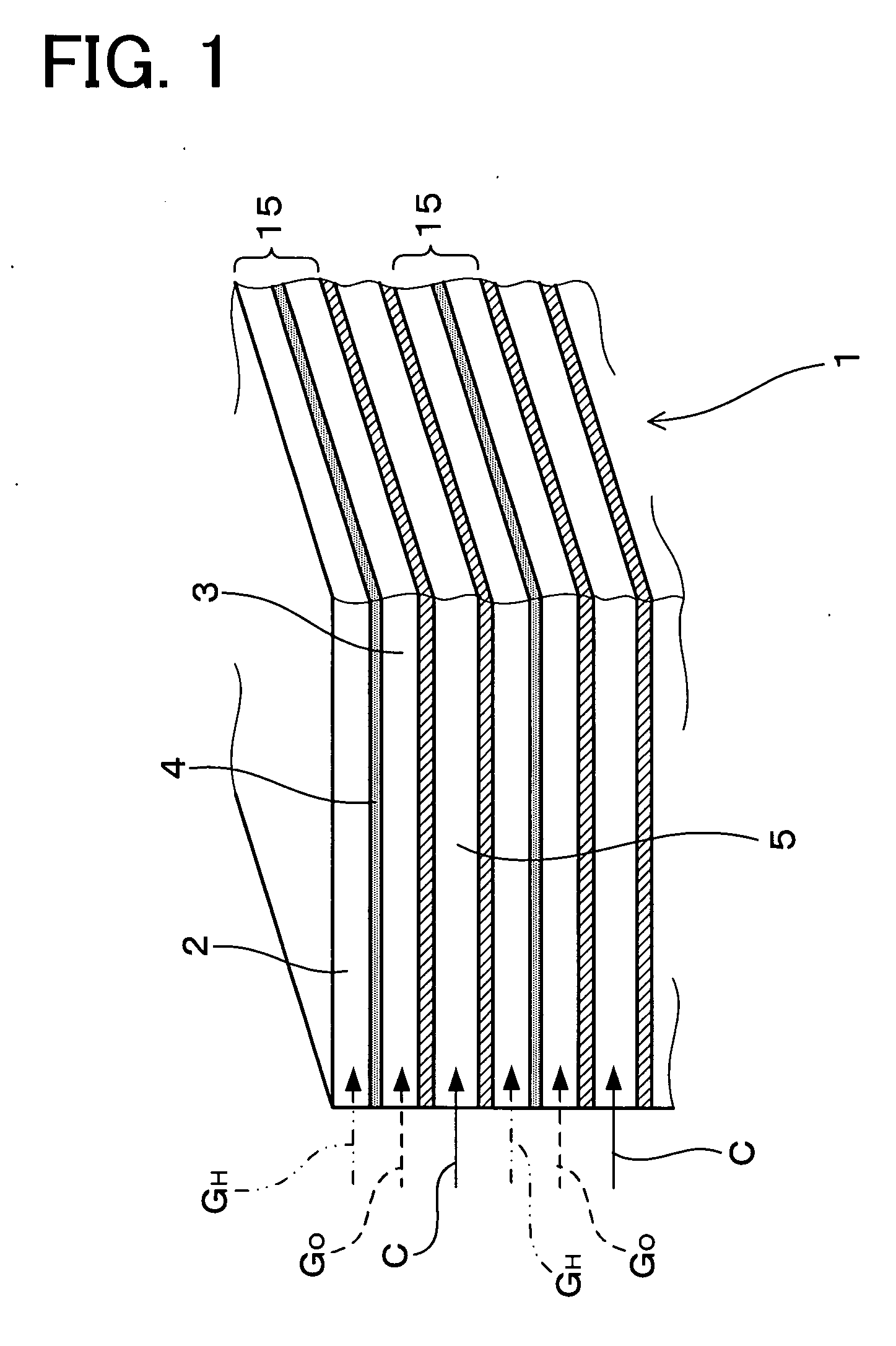
[0153] Now, a fuel cell according to an embodiment of the present invention will be described with reference to FIG. 1 to FIG. 3.

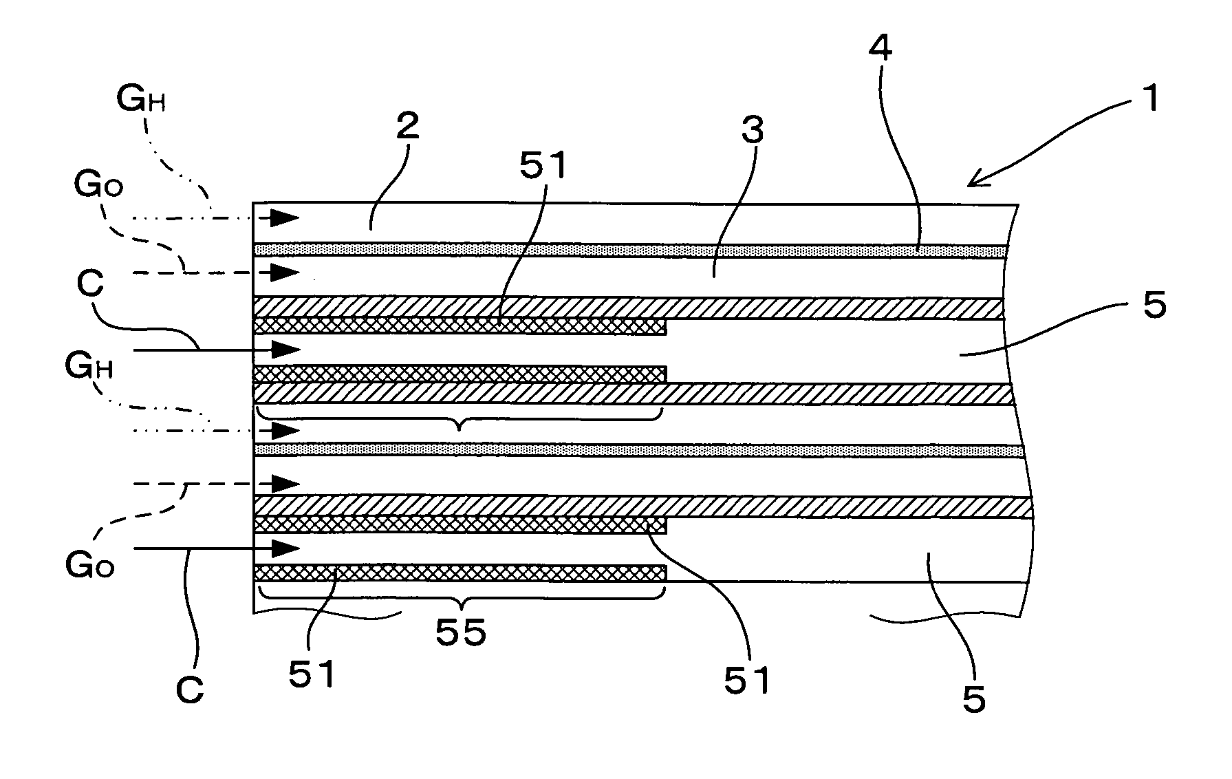
[0154] As shown in FIG. 1, a fuel cell 1 according to the present embodiment is made of a laminate of an anode channel 2 supplied with hydrogen or a hydrogen-containing gas GH; a cathode channel 3 supplied with oxygen or an oxygen-containing gas GO; and an electrolyte 4 arranged between the cathode channel 3 and the anode channel 2.

[0155] In addition, the fuel cell 1 according to the present embodiment is further made by laminating a plurality of unit battery cells 15 made by laminating an anode channel 2, an electrolyte 4, and a cathode channel 3.

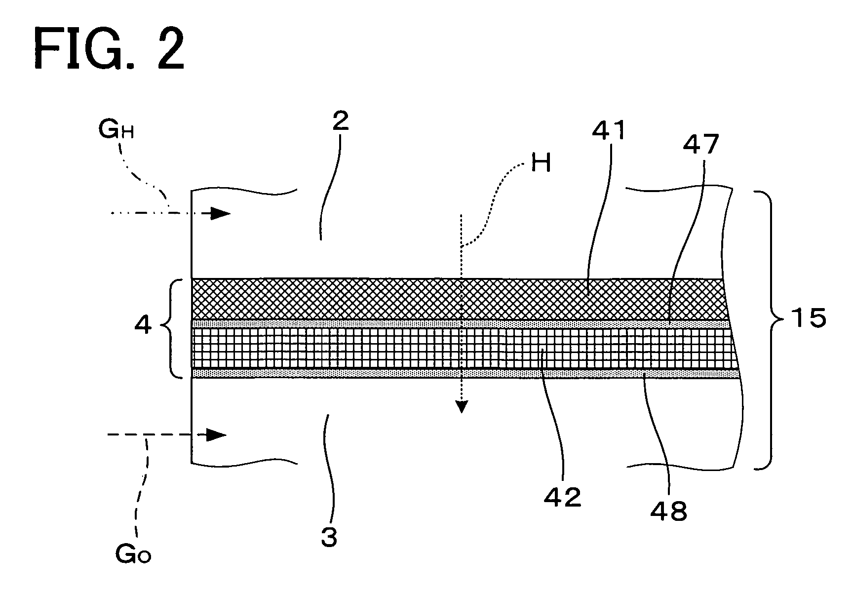
[0156] In addition, as shown in FIG. 2, the electrolyte 4 is made by laminating a hydrogen separating metal layer 41 for being permeated by hydrogen supplied to the anode channel 2 or hydrogen in the hydrogen-containing gas GH supplied to the anode channel and a proton conductor layer 42 made ...

second embodiment

[0175] In the present embodiment, the low heat conducting section in the coolant channel has been formed by providing a hollow section in a wall of a coolant channel.

[0176] That is, as shown in FIG. 4, in the fuel cell 1 according to the present embodiment, a hollow section 52 is formed by hollowing the wall at the inlet side of the coolant channel 5 partially. In this manner, the passing heat resistance at the inlet side of the coolant channel 5 can be increased. That is, a hollow section 52 is formed in the wall at the inlet side of the coolant channel 5, whereby the inlet side of the coolant channel 5 is obtained as a configuration such as thermos, and heat transfer of this section can be restricted.

[0177] Therefore, in the fuel cell 1 according to the present embodiment, as in the first embodiment, excessive cooling at the inlet side of the coolant channel 5 can be prevented, and cooling using the coolant C can be uniformly carried out. Therefore, the deviation in temperature ...

third embodiment

[0178] In the present embodiment, the low heat conducting section in the coolant channel has been formed by providing a replacement restricting section.

[0179] That is, as shown in FIG. 5, in the fuel cell 1 according to the present embodiment, a replacement restricting section 551 for restricting replacement of the coolant C is formed at the inlet side of the coolant channel 5, thereby forming a low heat conducting section 55. As shown in the figure, the replacement restricting section 551 is formed by providing a hollow section 52 provided in the wall at the inlet side of the coolant C in the coolant channel 5 and openings 521 and 522 provided in the hollow section 52 and opened in the coolant channel 5.

[0180] Specifically, as shown in FIG. 5, the inside of the wall at the inlet side of the coolant C in the coolant channel 5 is hollowed to form the hollow section 52, and the openings 521 and 522 that open in the coolant channel 5 are formed at hollow section 52. As shown in the f...


PUM

PropertyMeasurementUnit
temperatureaaaaaaaaaa
operating temperatureaaaaaaaaaa

Abstract

A fuel cell is made by laminating an anode channel 2 supplied with hydrogen or a hydrogen-containing gas gH, a cathode channel 3 supplied with oxygen or an oxygen-containing gas GO, and an electrolyte 4 arranged between the cathode channel and the anode channel. The electrolyte 4 is made by laminating a hydrogen separating metal layer for making hydrogen supplied to the anode channel 2 or hydrogen in a hydrogen-containing gas GH supplied to the anode channel 2 permeate; and a proton conductor layer made of ceramics, for establishing the hydrogen having permeated the hydrogen separating metal layer in a proton state and making it reach the cathode channel 3. In addition, the fuel cell has a coolant channel 5 for cooling the fuel cell 1. In the coolant channel 5, a low heat conducting section 55 having a heat conductivity smaller than that at a downstream side of a coolant C is formed at an inlet side of the coolant C.

Description

CROSS-REFERENCES TO RELATED APPLICATIONS [0001] This application is a continuation of Application PCT / JP2004 / 017181, filed Nov. 18, 2004 which claims priority under 35 U.S.C.§119 to Japanese Patent Application No. 2003-400255, filed Nov. 28, 2003, entitled “FUEL CELL”. The contents of this application are incorporated herein by reference in their entirety.TECHNICAL FIELD [0002] The present invention relates to a fuel cell for generating electric power by utilizing hydrogen and oxygen. In particular, the present invention relates to a fuel cell comprising a coolant channel for cooling the battery. BACKGROUND ART [0003] A fuel cell system for generating electric power by utilizing a hydrocarbon fuel or the like comprises a reformer for generating a hydrogen-containing gas from a hydrocarbon fuel or the like, a hydrogen separating membrane device for removing hydrogen with high purity from the hydrogen-containing gas, and a fuel cell for generating electric power by establishing hydrog...

Claims


Application Information

Patent Timeline
Patent Type & Authority Applications(United States)
IPC IPC(8): H01M8/10H01M8/04H01M8/02H01M8/06H01M8/12
CPCH01M8/0267H01M8/04007H01M8/04067H01M8/0662Y02E60/525H01M8/1206H01M2008/1293H01M2300/0074Y02E60/521H01M8/0687H01M8/1231Y02E60/50H01M8/0265H01M8/0258
Inventor OGINO, SHIGERUAOYAMA, SATOSHISHIOKAWA, SATOSHISHIMAZU, TAKASHIAOKI, HIROSHIMITSUI, HIROYUKI
Owner TOYOTA JIDOSHA KK
Why Eureka
Try Eureka